🧩 Assembly
It is highly reccommended that you read this entire assembly manual to familiarize yourself before starting!
Overview
The assembly process consists of 20 easy steps, which should take up to 60 minutes per device.
The device was designed for not needing wire soldering, glueing or any other complex operation.
You will be installing brass inserts into plastic, placing parts together, connecting cables and fastening screws.
Safety
- Be aware of the soldering iron tip and hot parts to avoid burning yourself and the 3d printed parts.
- The metal inserts will keep hot for a while after inserting, especially the bigger 1/4" ones.
Step 1 – Setup and Preparation
- make sure there is enough space and lighting;
- have all parts and components accessible on bench, placing the smallest ones on "buckets" to avoid losing them;
- leave the center of the bench for where the actual work is going to be, and the perimeter for tools and other parts;
- keep dangerous tools such as the soldering station away from where you could accidentaly hit it by mistake.
Meanwhile, you can always consult the overview reference, bill of materials and suggested tools throughout the process.
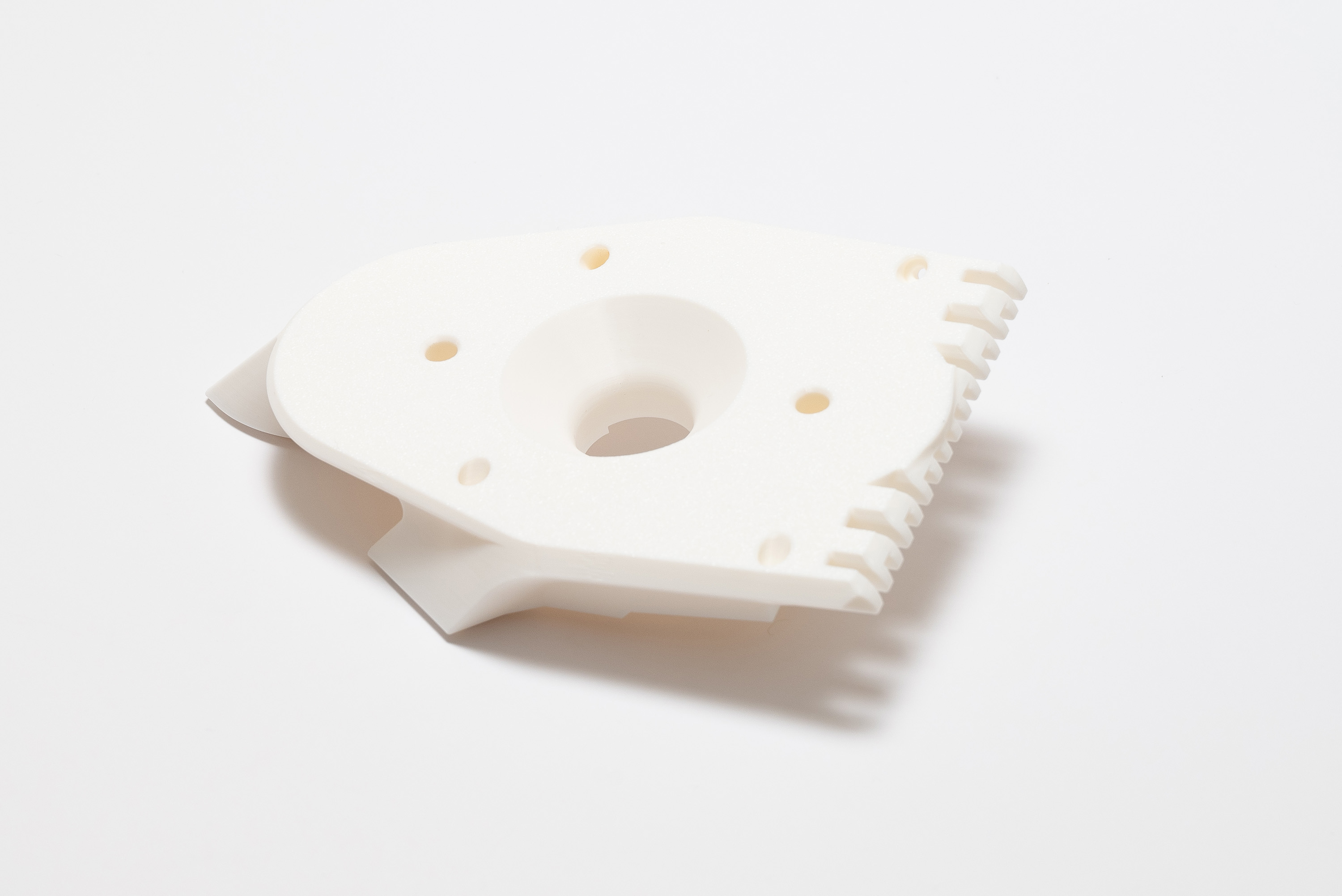
Step 2 – Remove Printed Supports
Remove the support on middle piece:
Remove the support on camera piece:
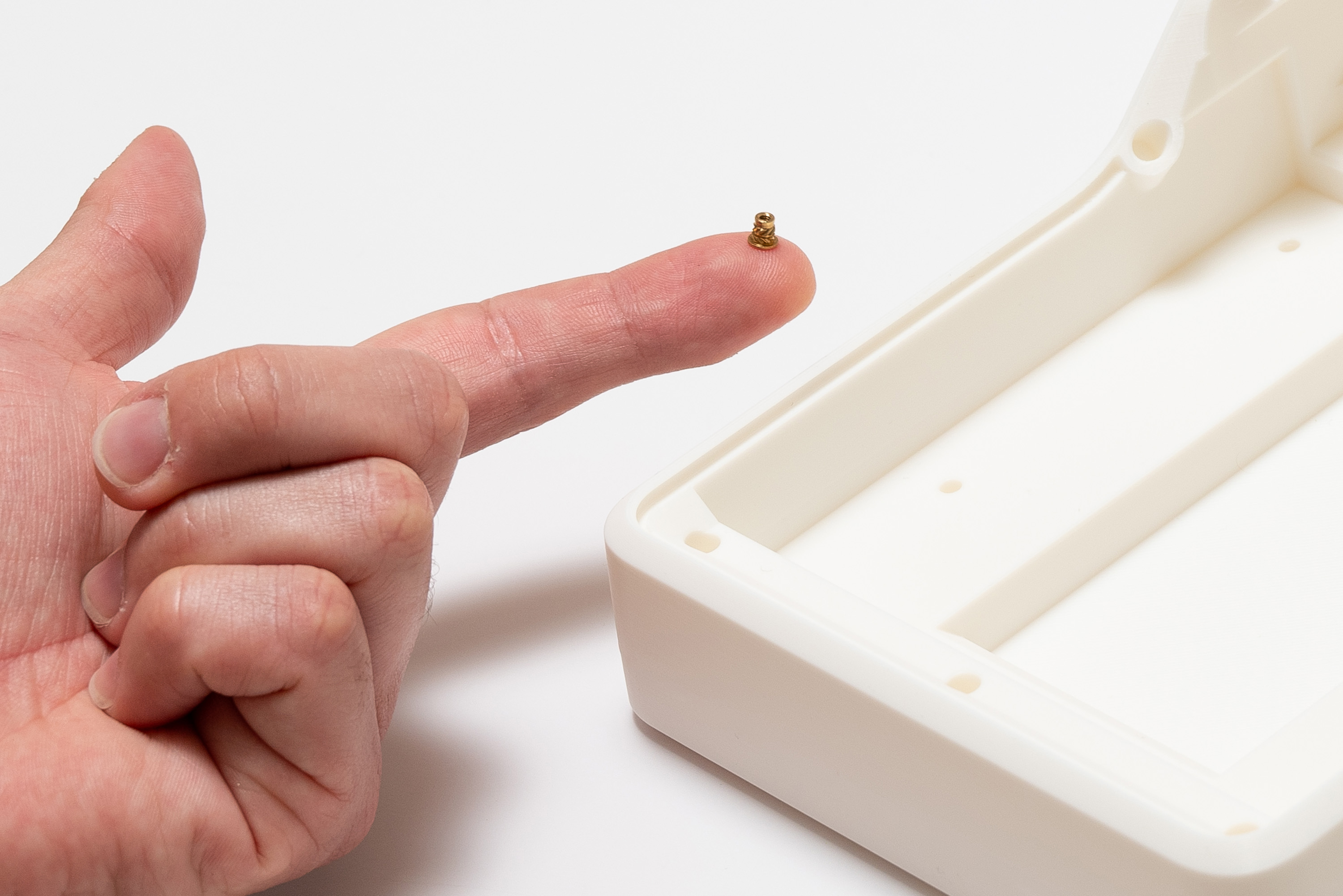
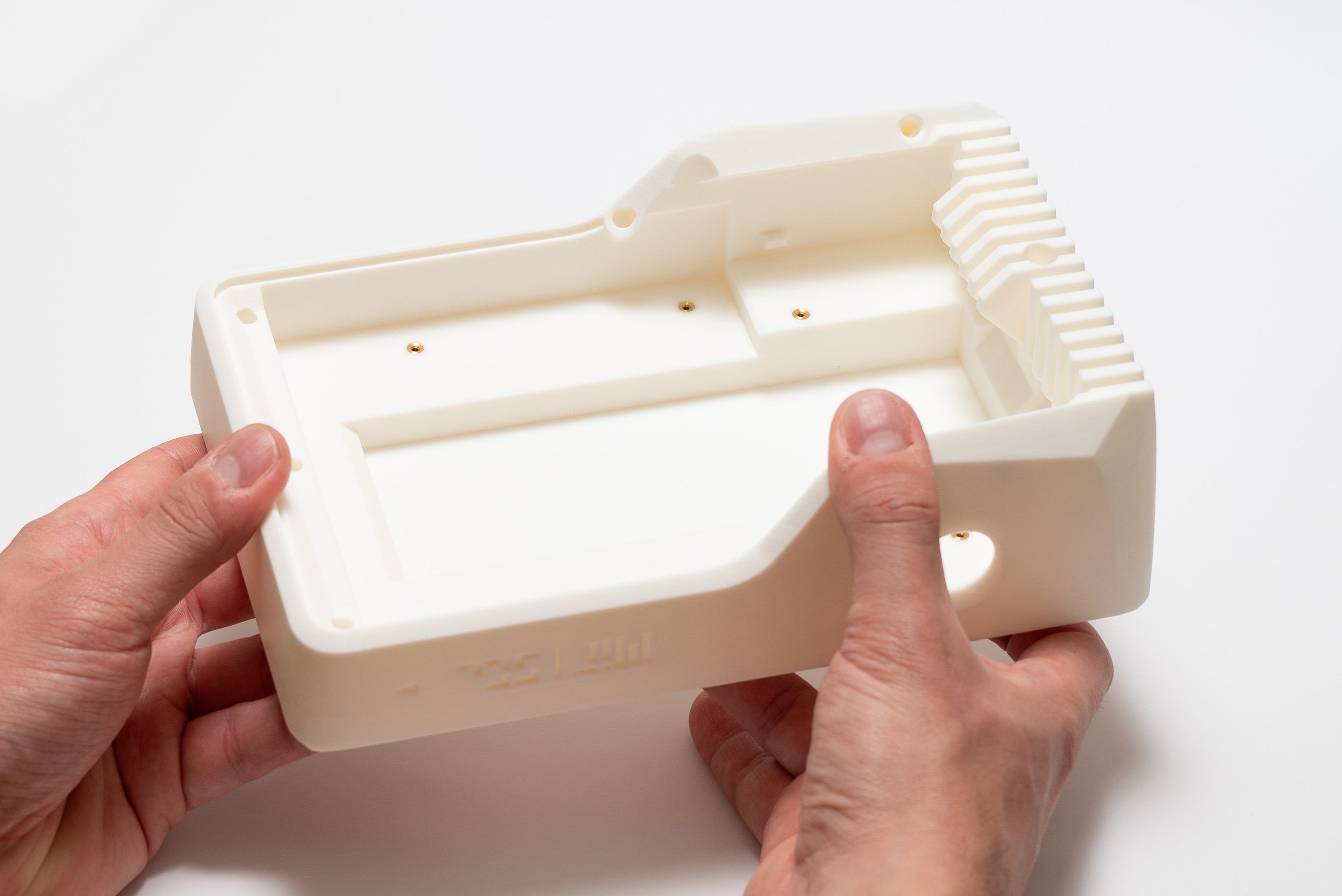
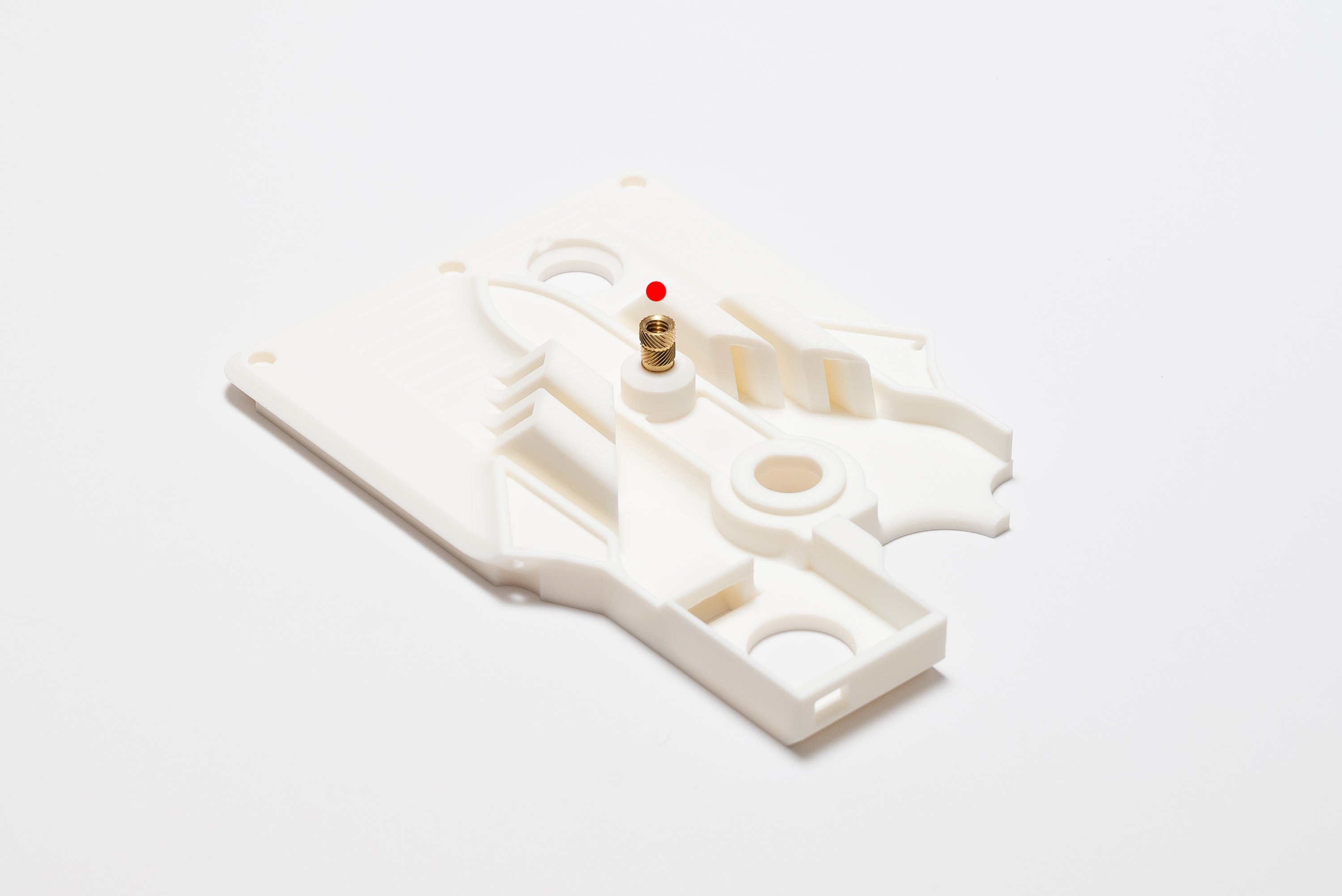
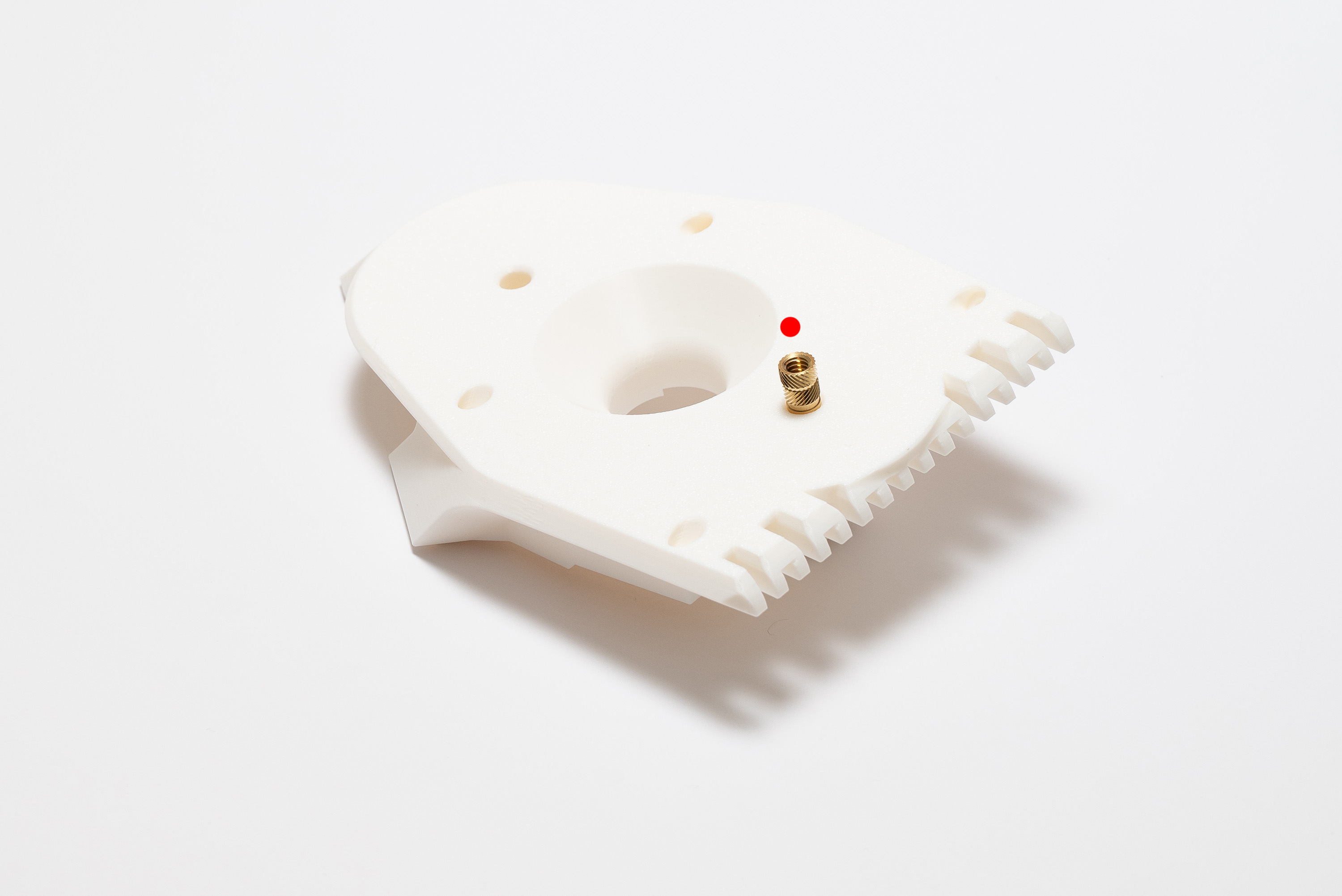
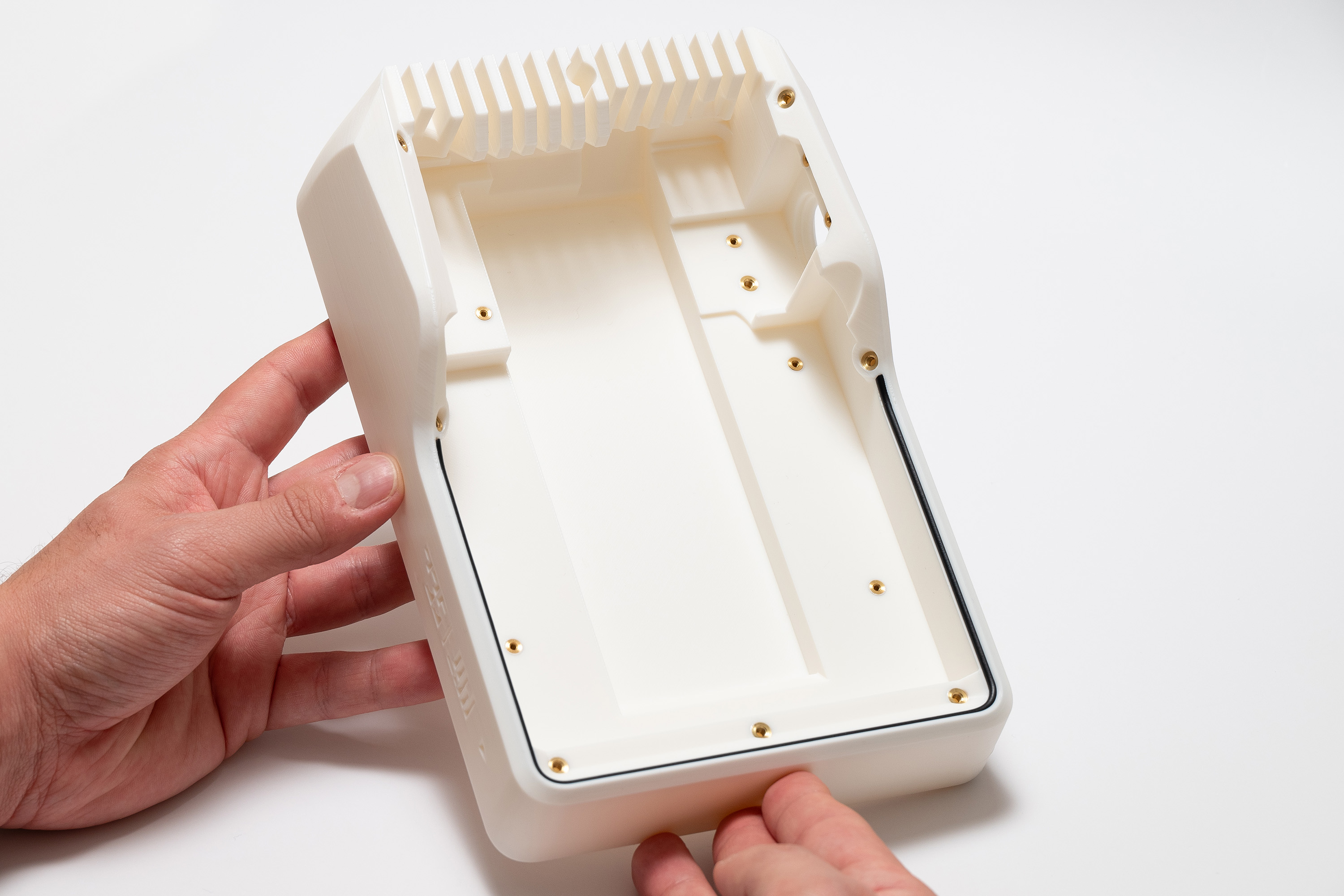
Step 3 – M2 Inserts
- It is easy to misplace the inserts, pay attention to the indicated spots on the images.
- The larger holes are meant for the 1/4" inserts, the medium for M3 and smaller for M2.
- After the inserts are melted into the plastic they cannot be easily removed without damaging the 3d printed part.
- If in doubt, think twice and check the instructions!
Start by picking-up all the 13x M2 inserts
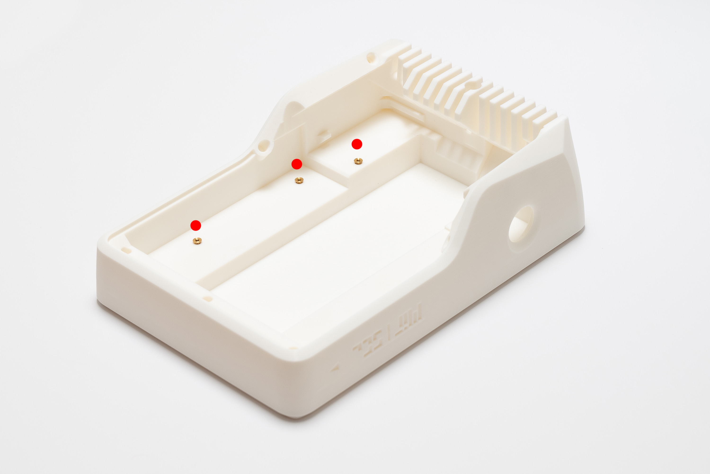
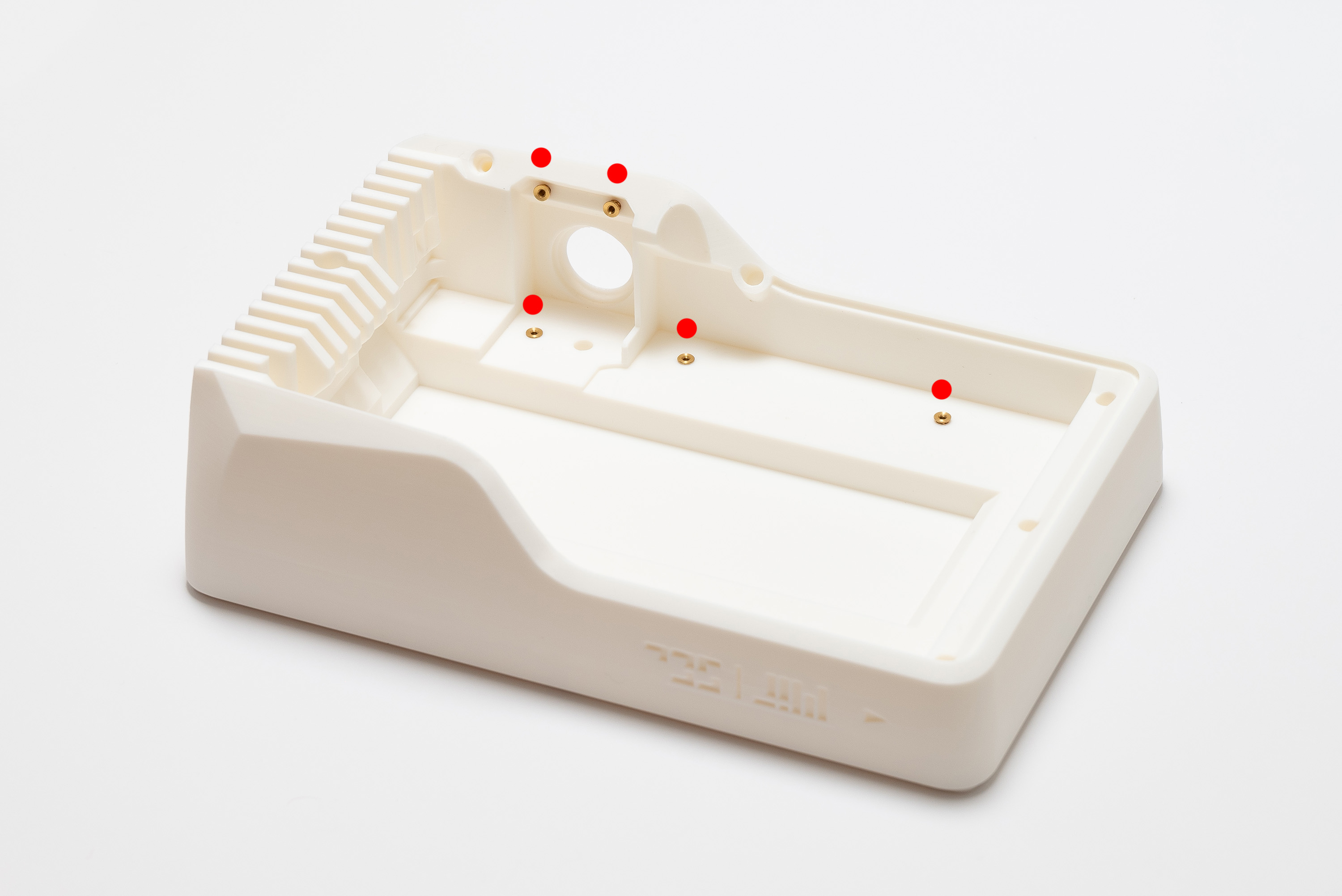
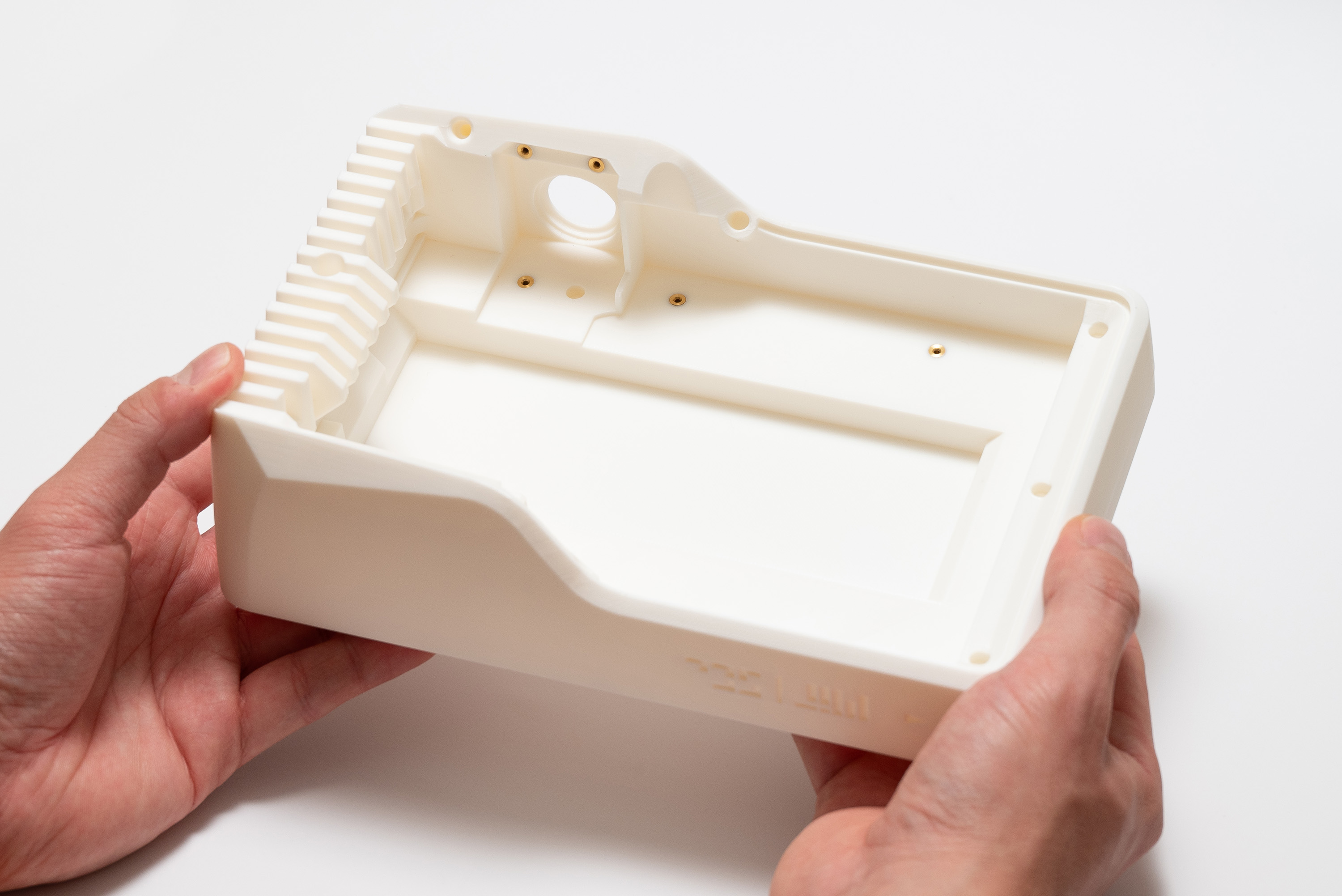
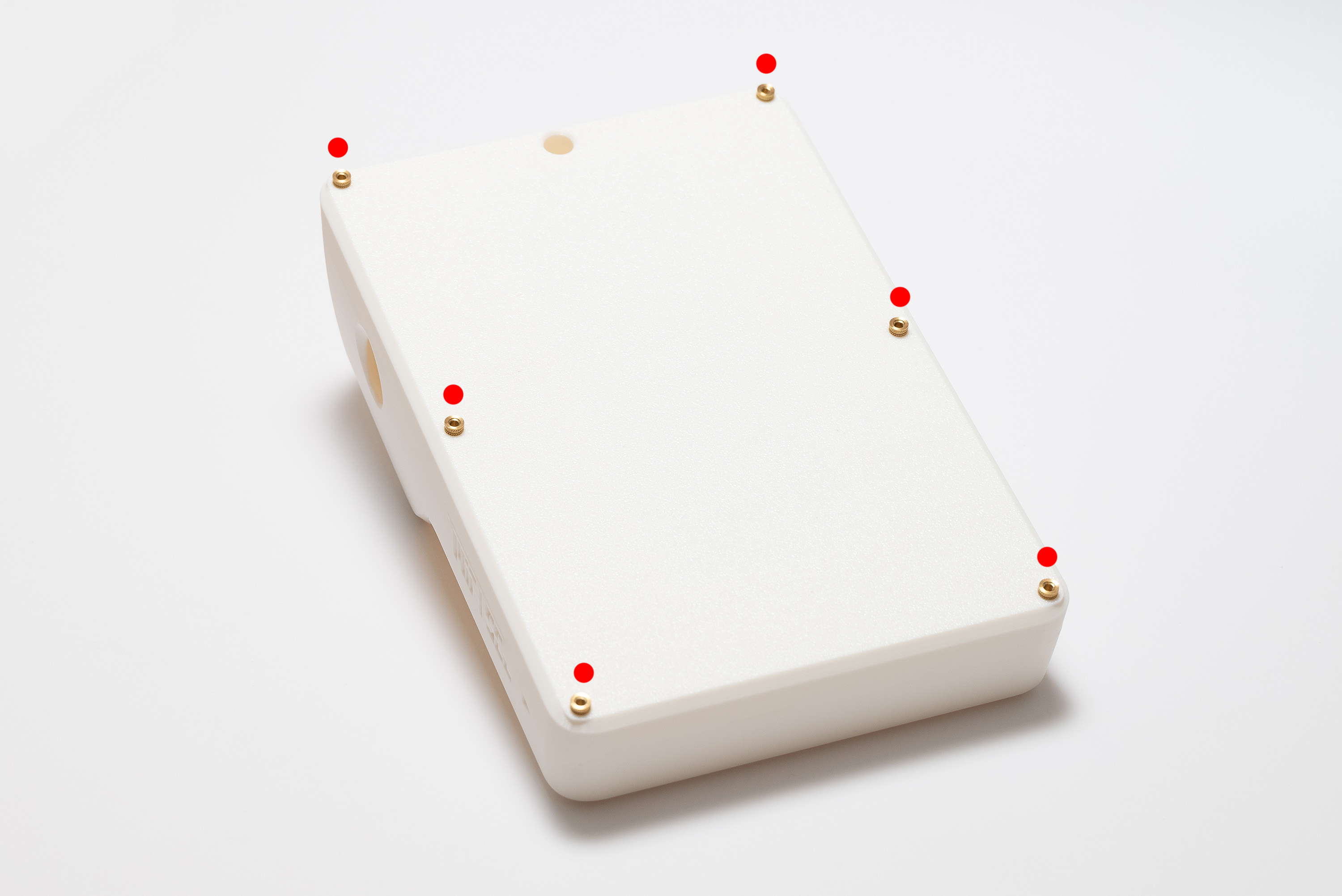
Of which, place 8x M2 inserts on top:
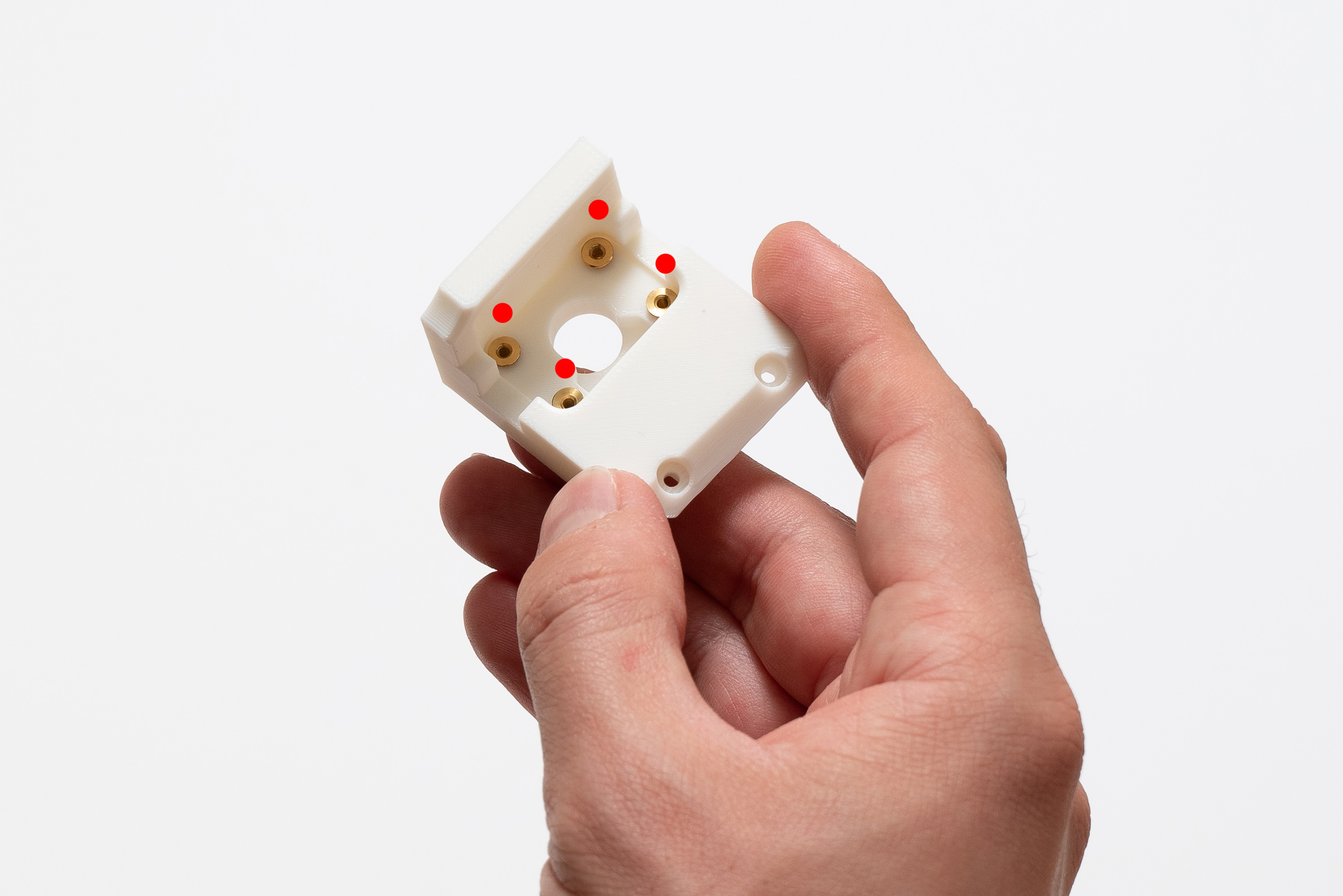
Then, place 4x M2 inserts on camera:
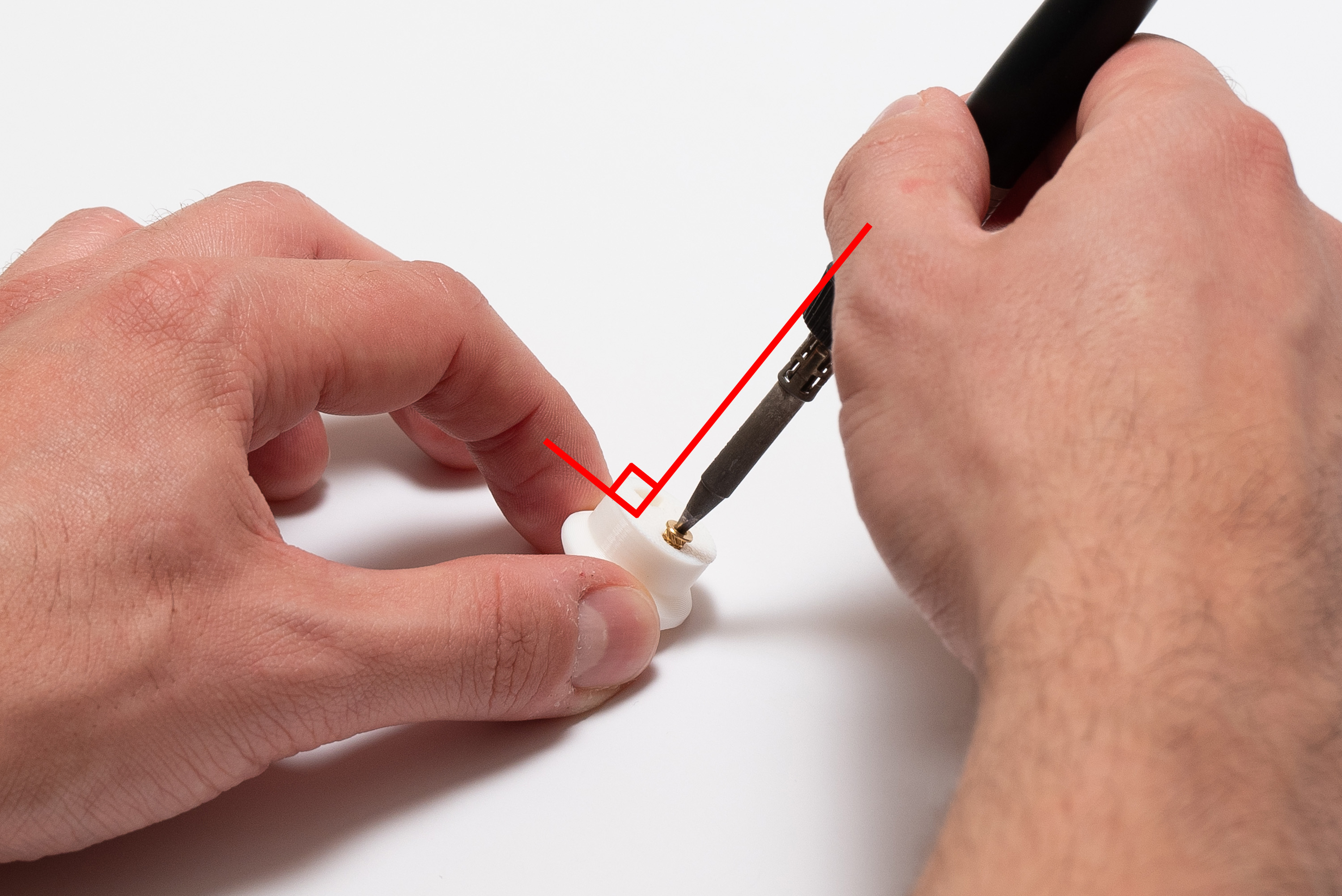
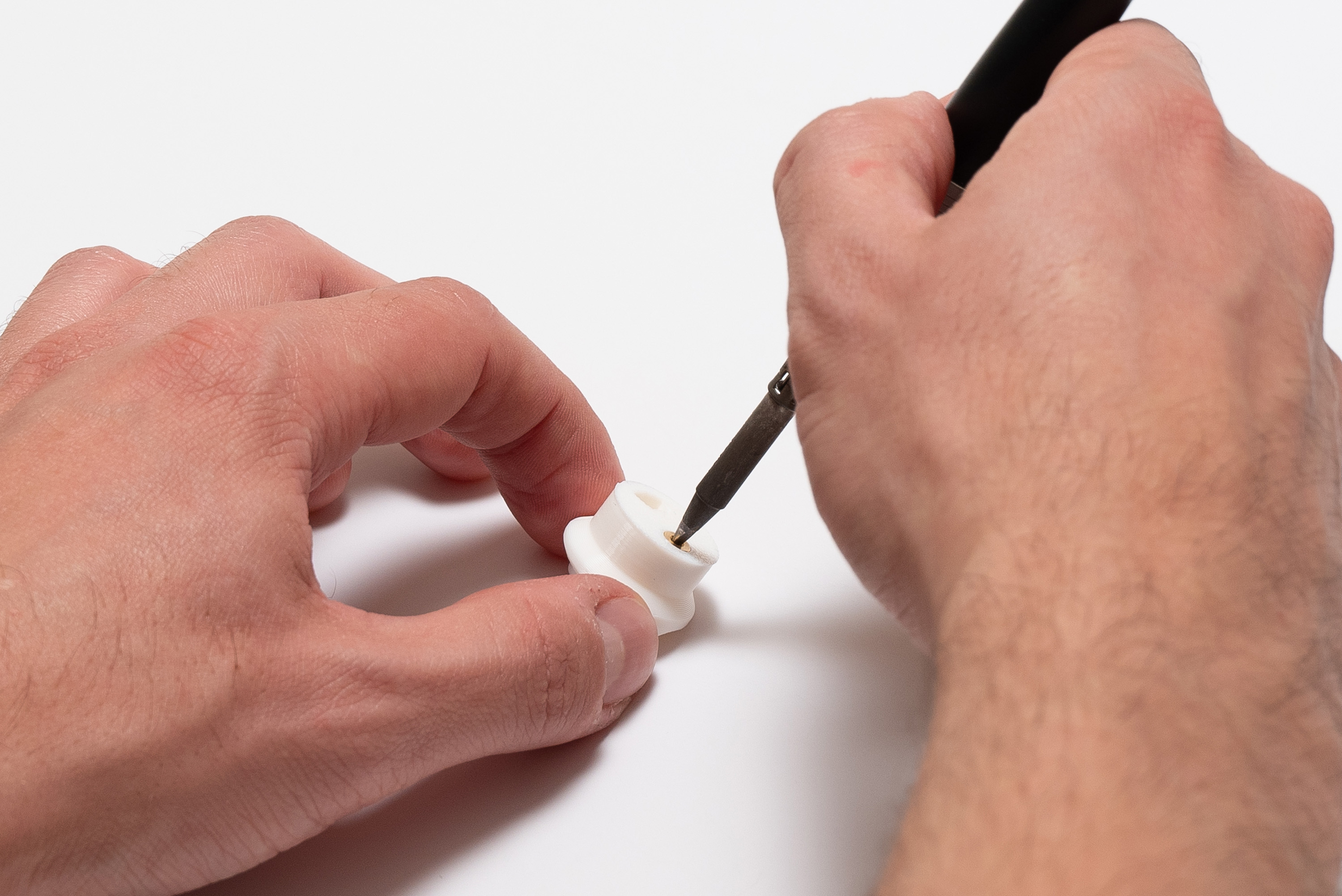
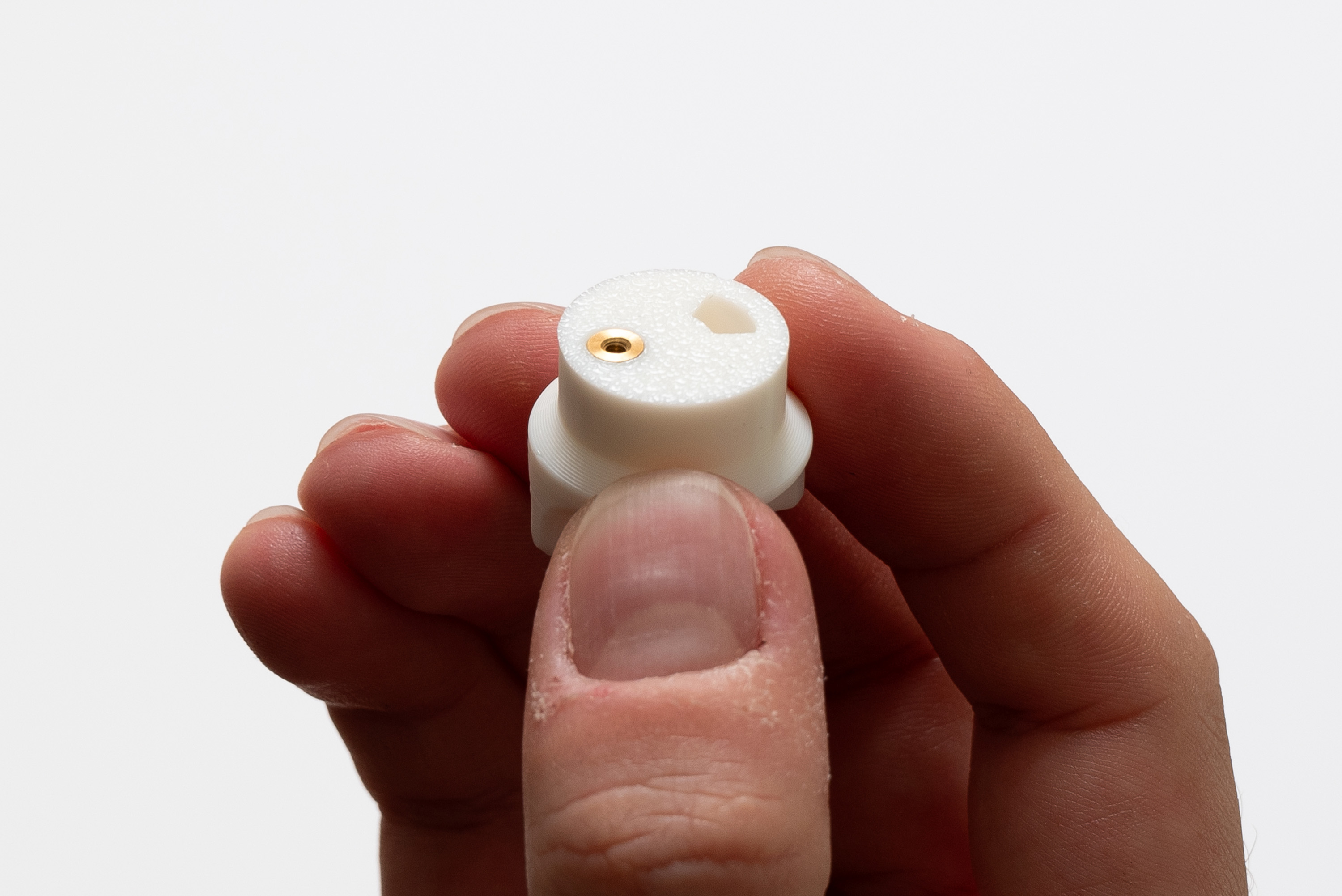
Finally, place the last 1x M2 insert on switch_bottom:
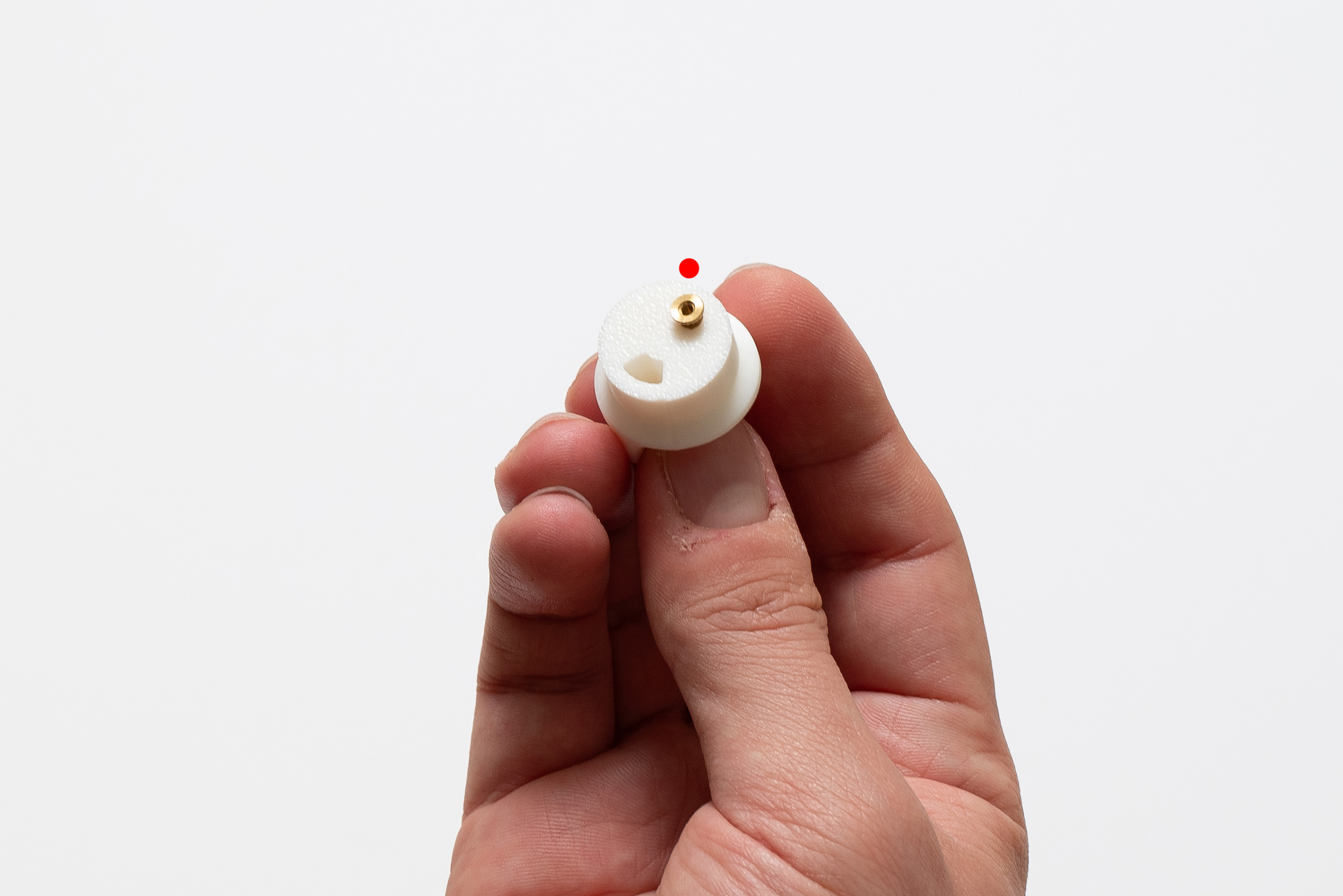
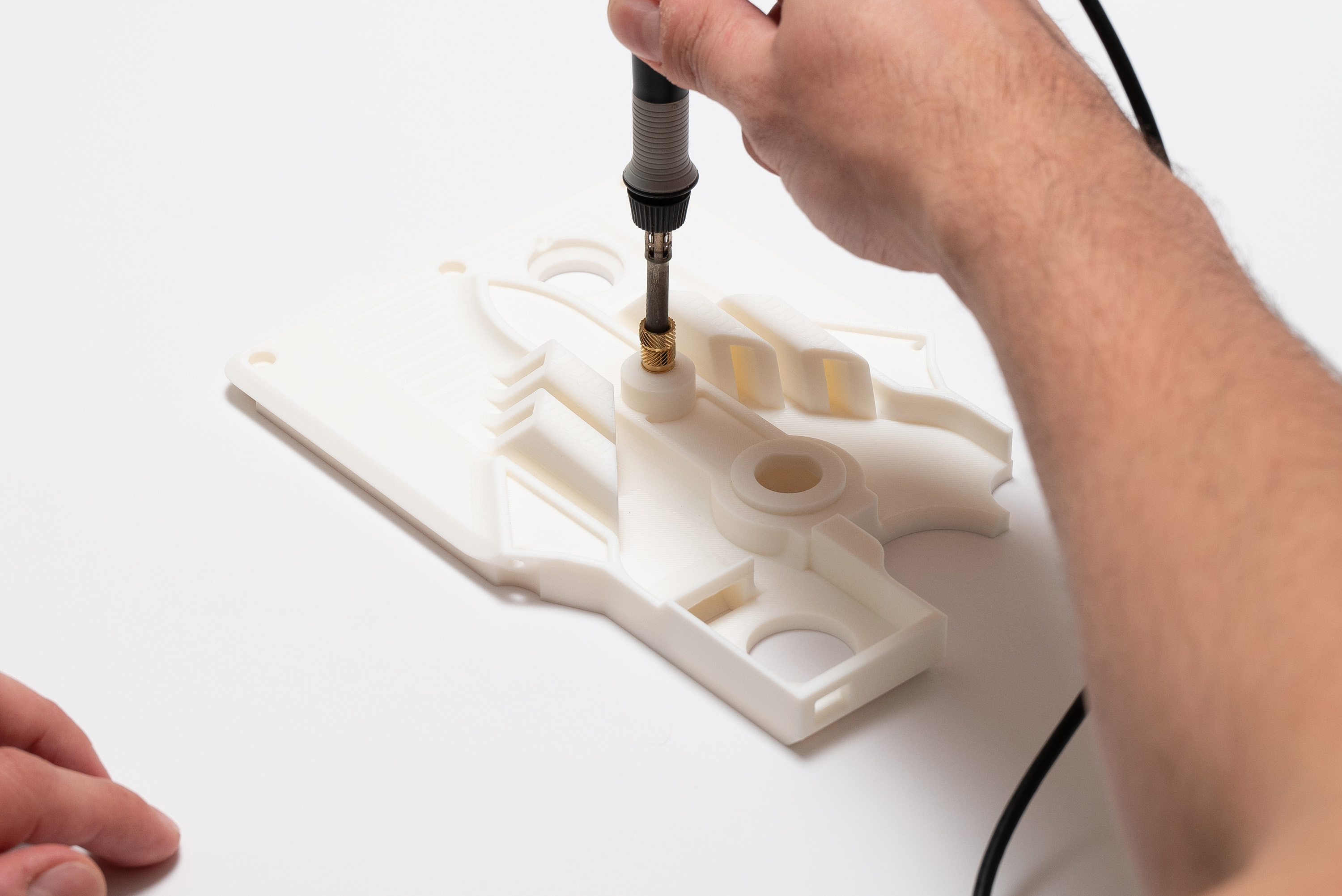
Set the soldering iron to 300ºC, wait for it to reach the temperature, then slowly press the soldering tip perpendicularly (avoid twisting) to the inserts until all them are flush with the printed surfaces:
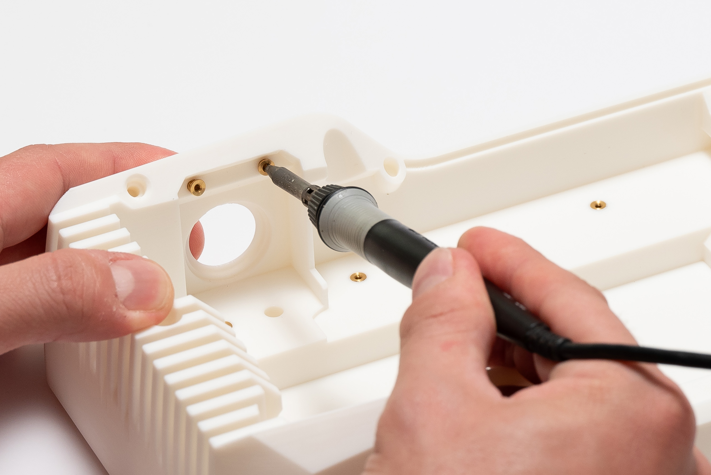
In the end, this should be the result:
✅ switch_bottom
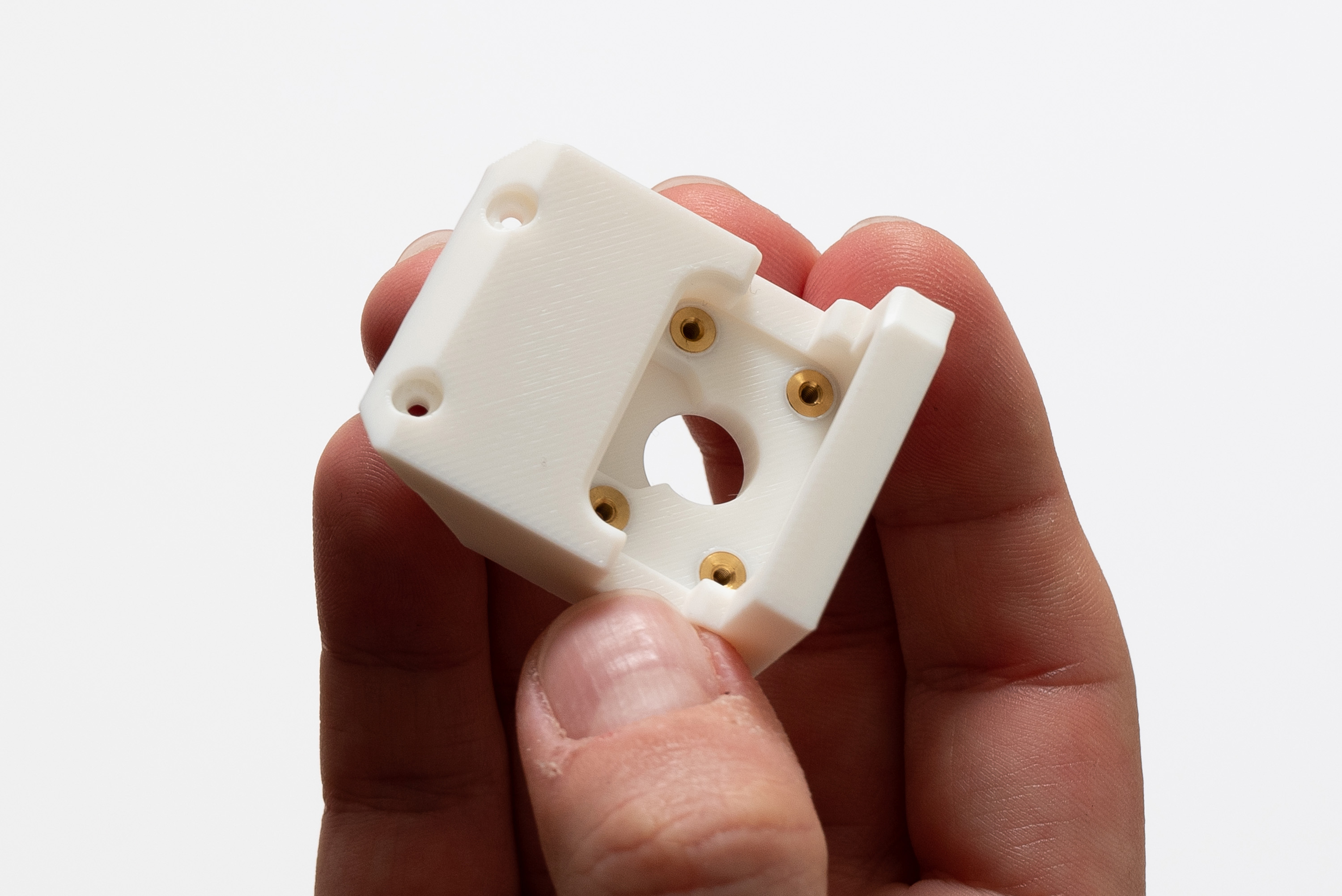
✅ camera
✅ top
Step 4 – M3 Inserts
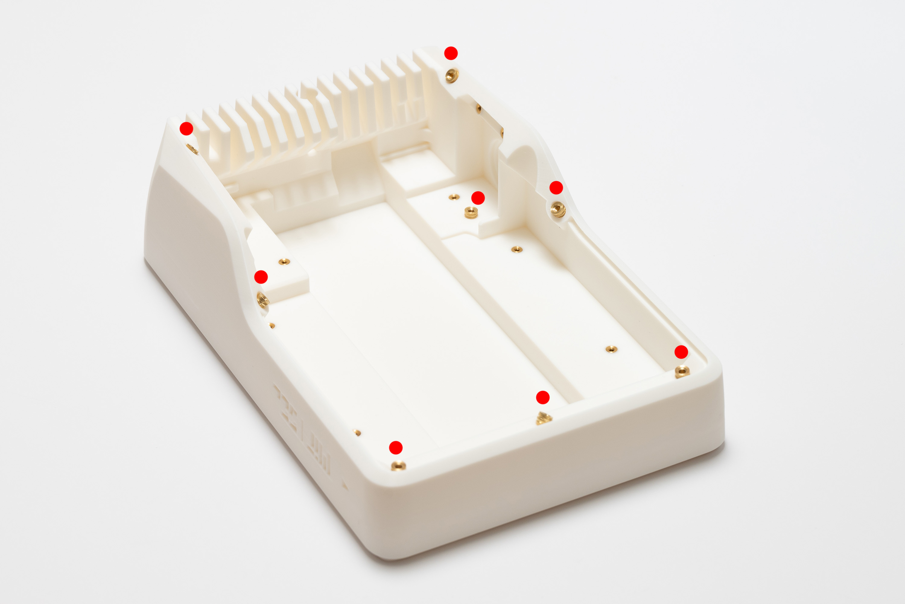
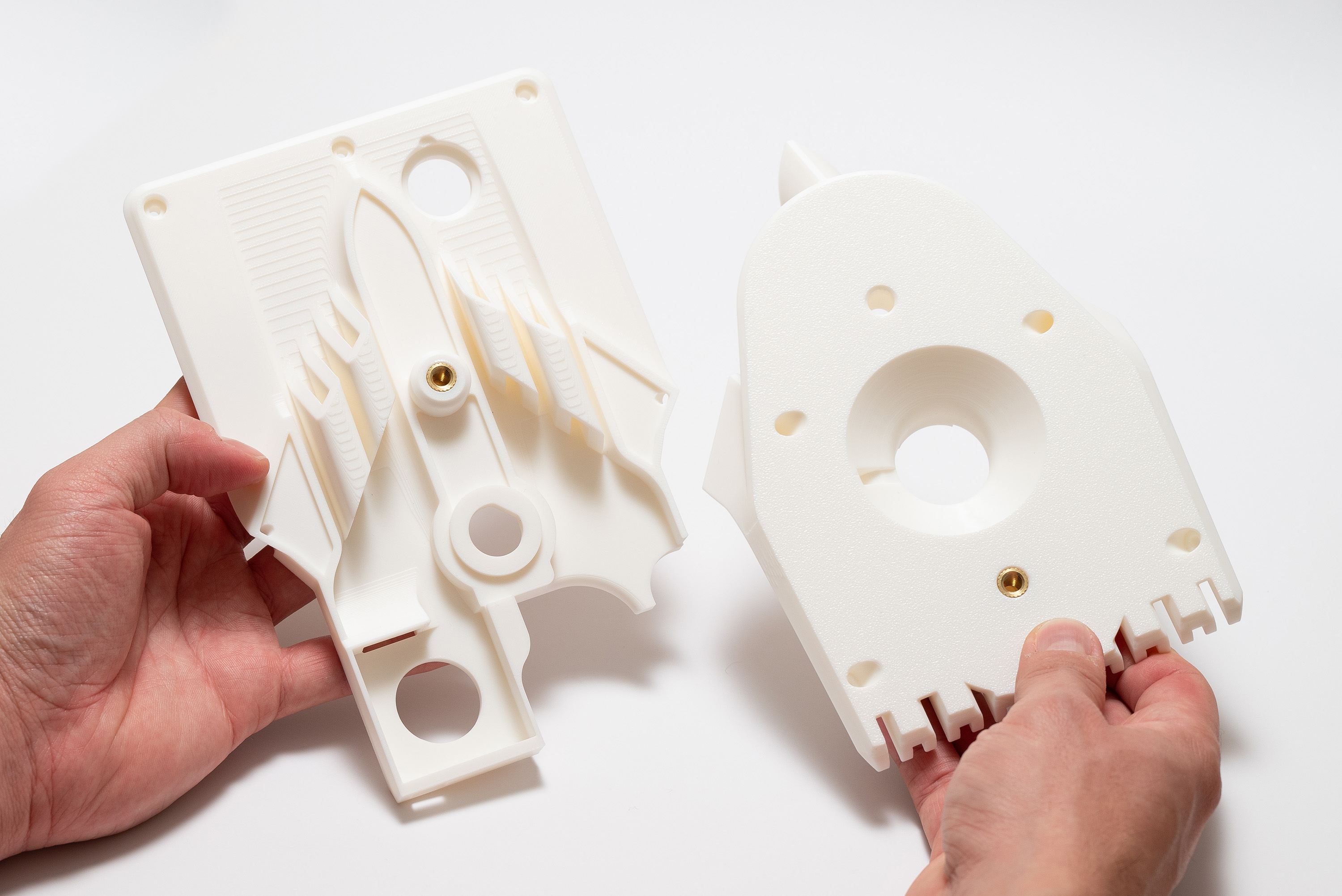
Pick-up 13x M3 inserts, turn the top piece around, then place 6x M3 inserts on it:
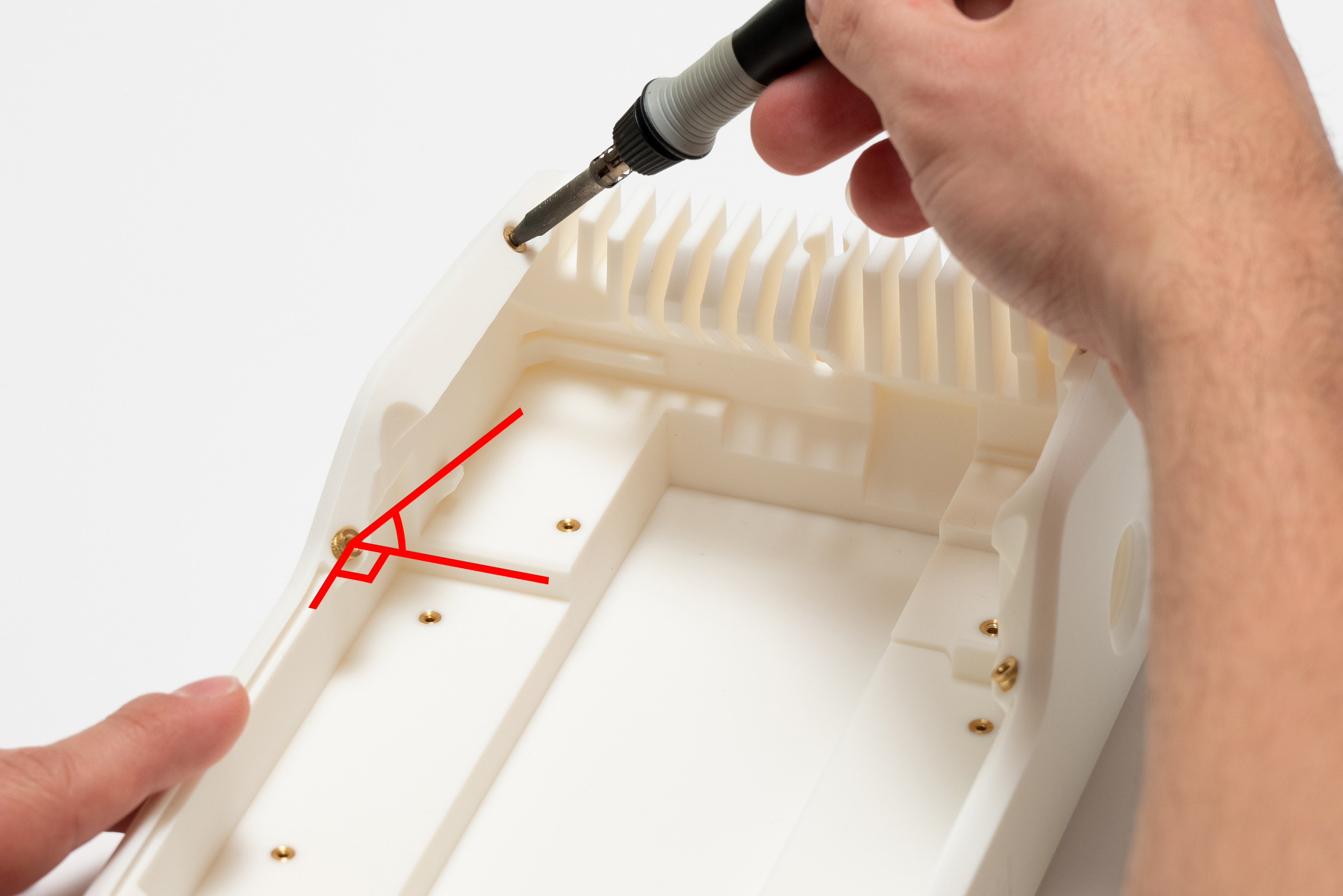
Then, install the 6x inserts with the soldering iron, turn the top piece back and place the remaining 8x M3 inserts on the other side:
Pay attention to the appropriate angle, respecting the holes' directions and the surface alignment:
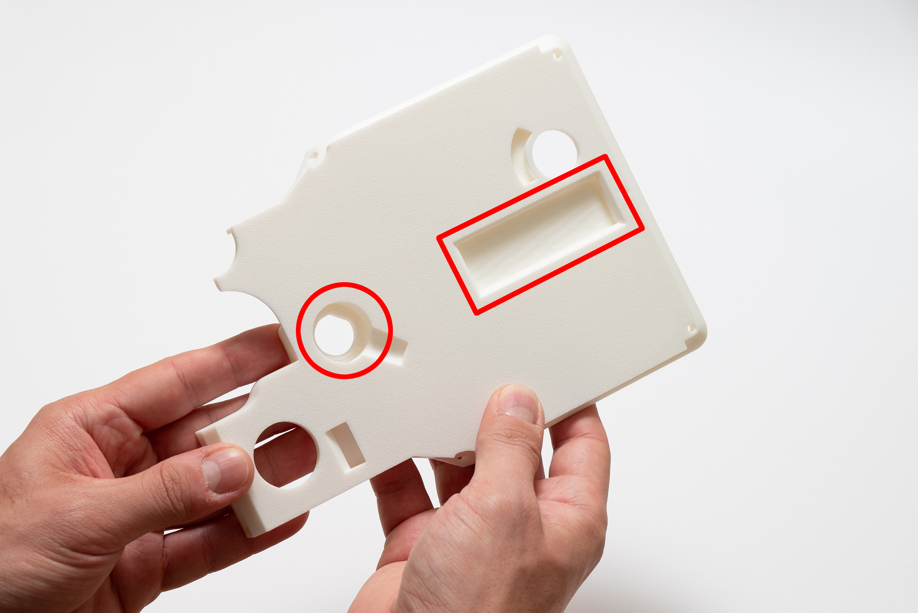
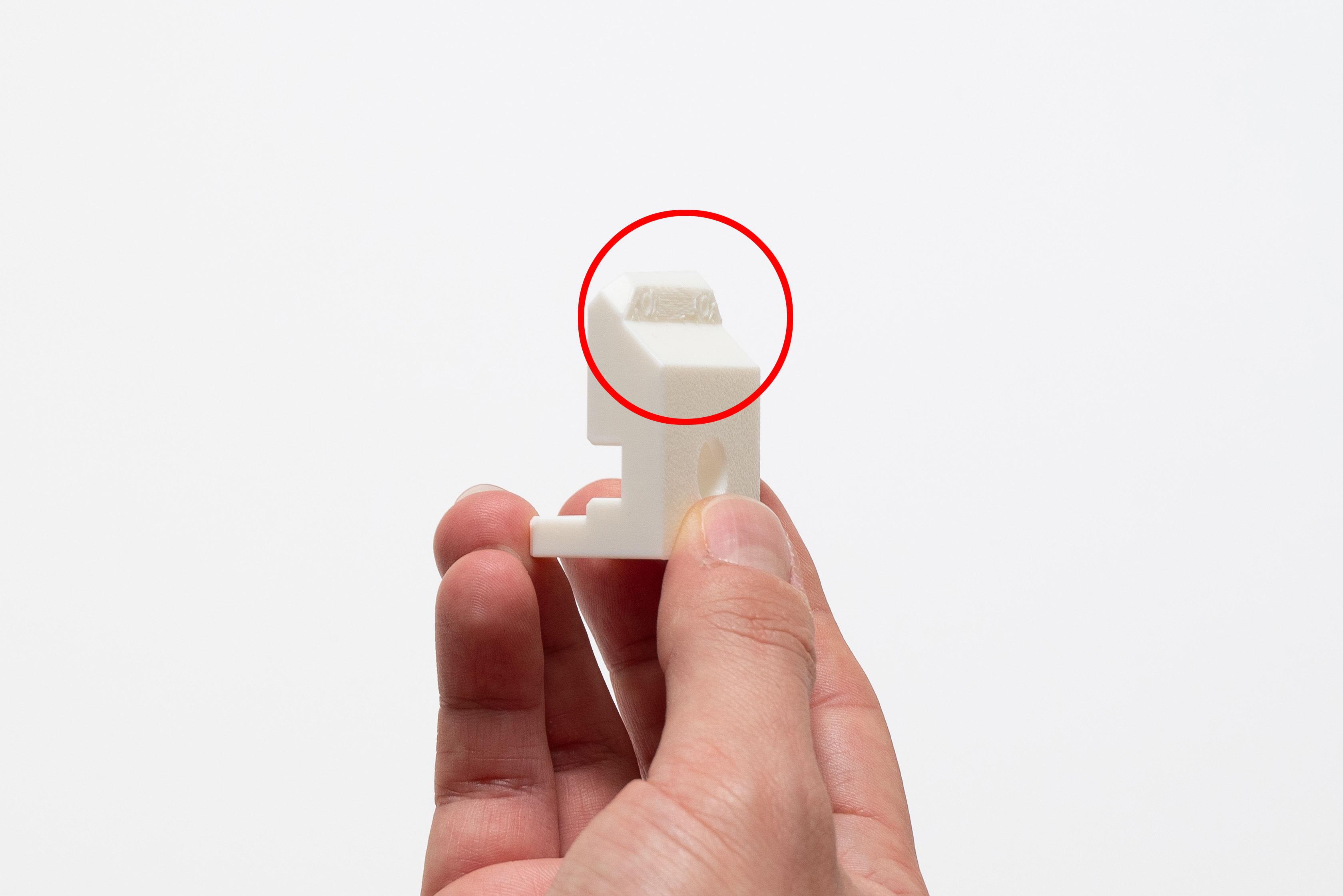
Step 5 – 1/4" Inserts
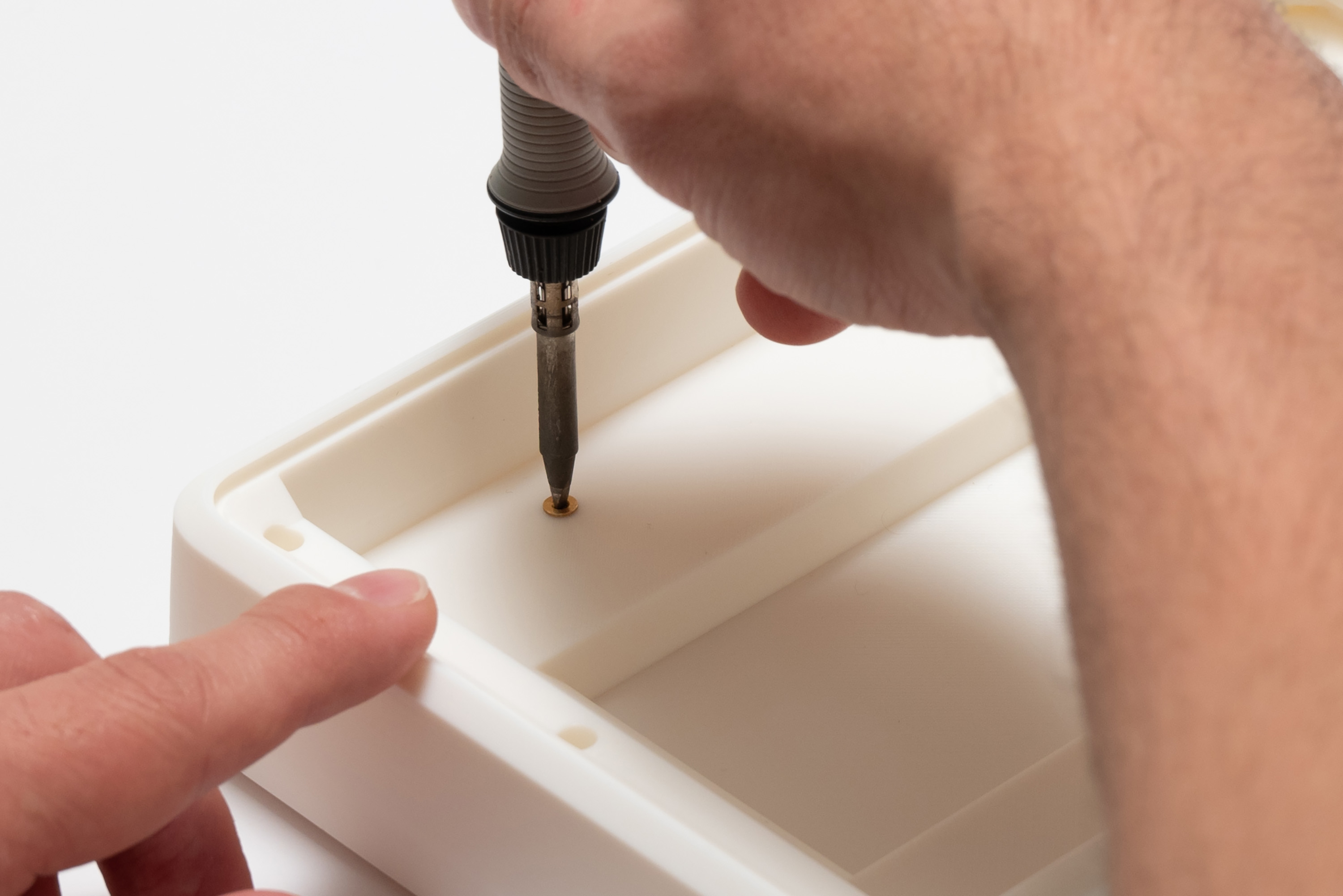
Place 1x ¼" insert on the designated spot on middle piece:
Be careful, these bigger inserts take longer to heat and to cool down.
Then, place the other ¼" insert on the rear spot of the bottom piece:
Be careful to not place the insert in the wrong spot
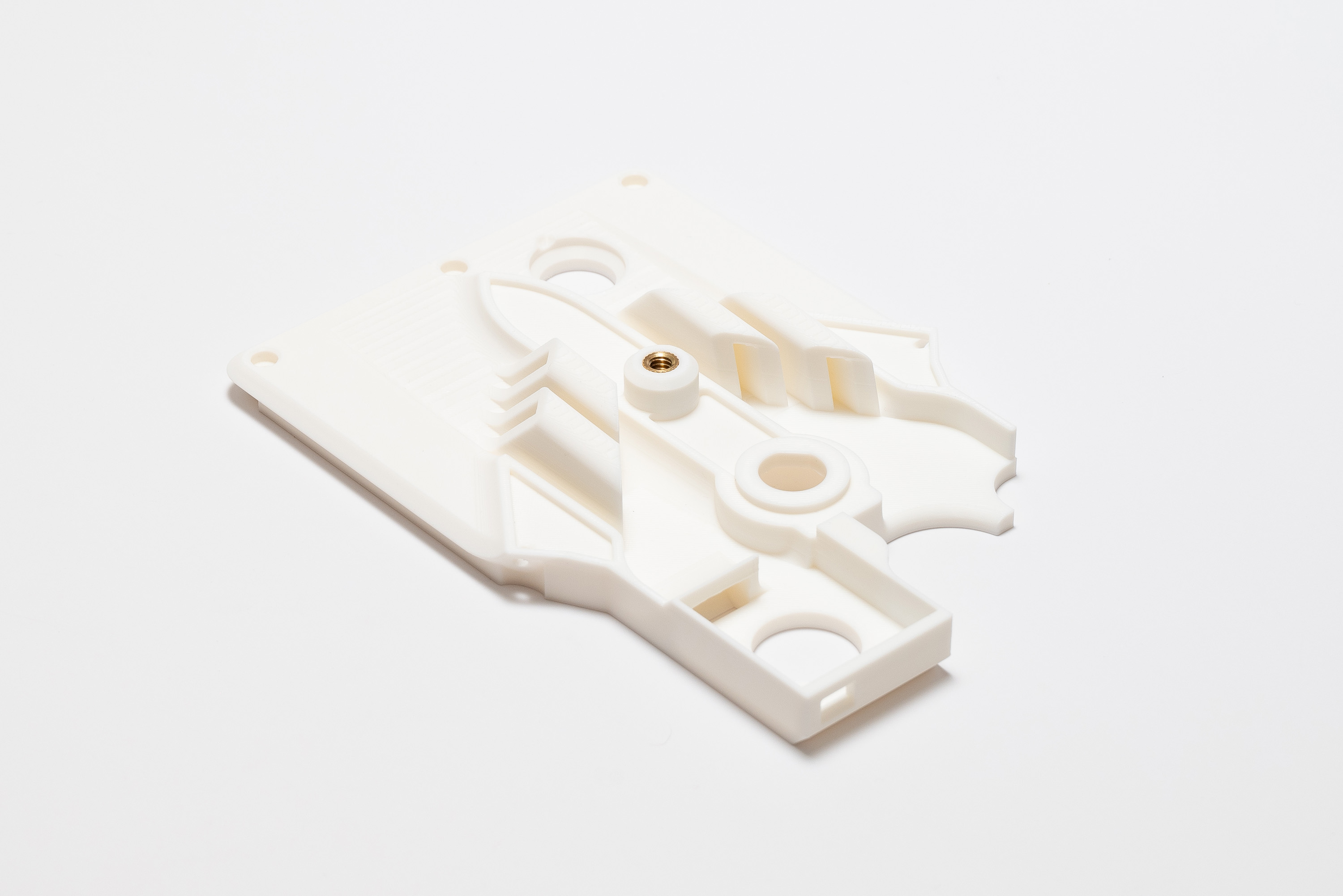
✅ Result
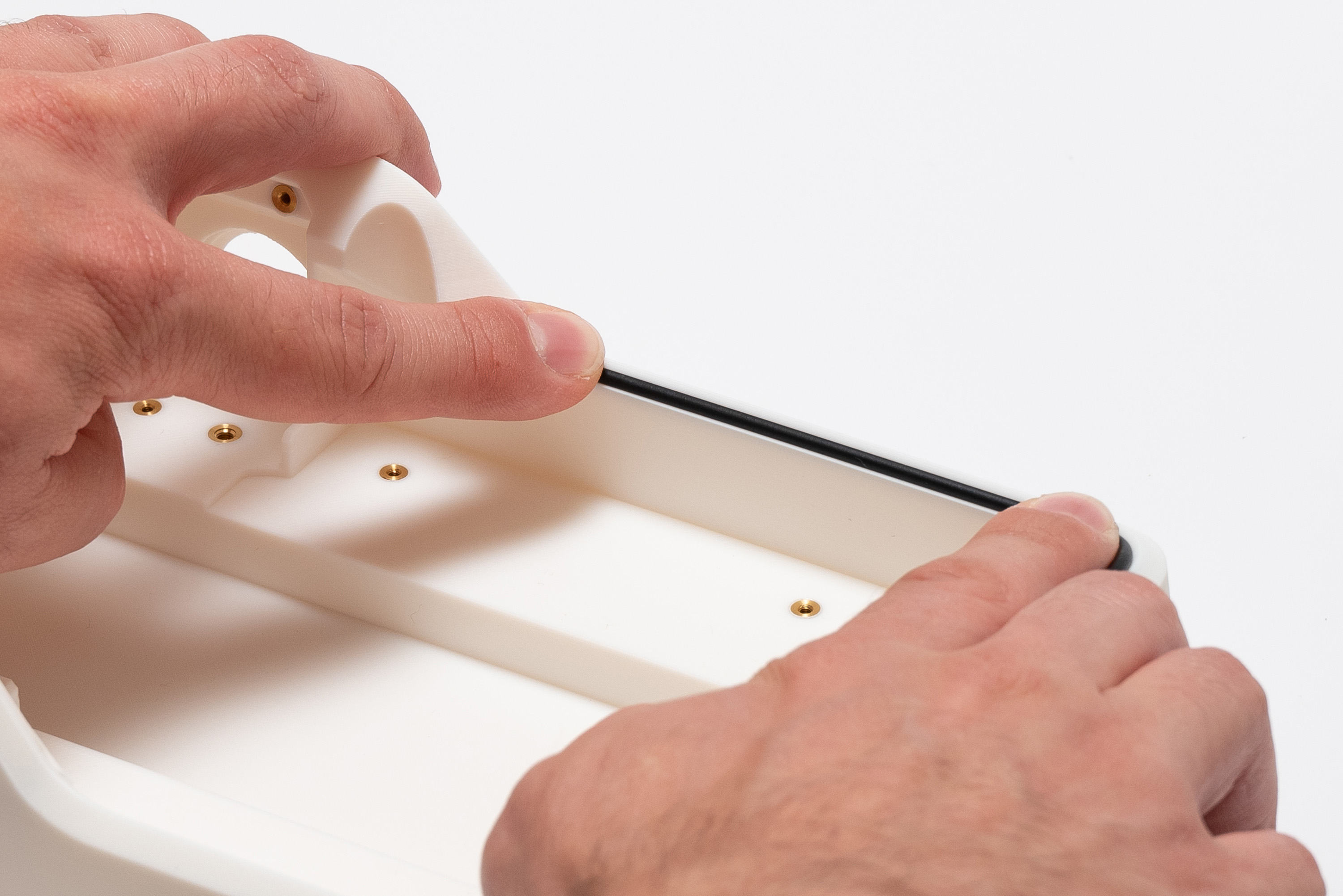
Step 6 – O-Ring Cord
Pick the O-ring cord and unroll it:
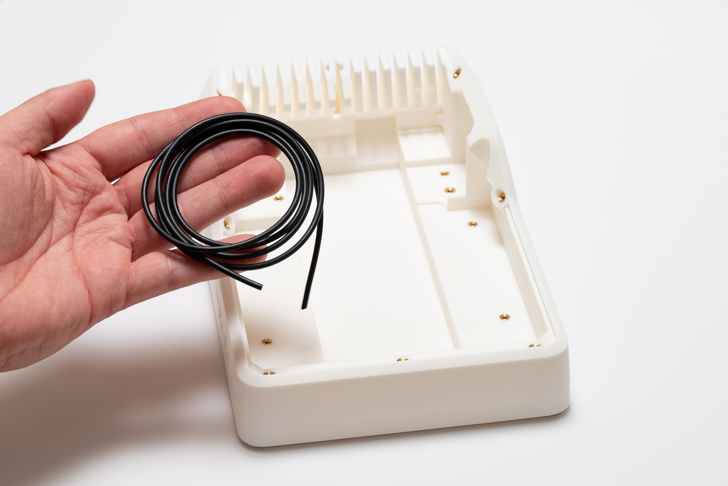
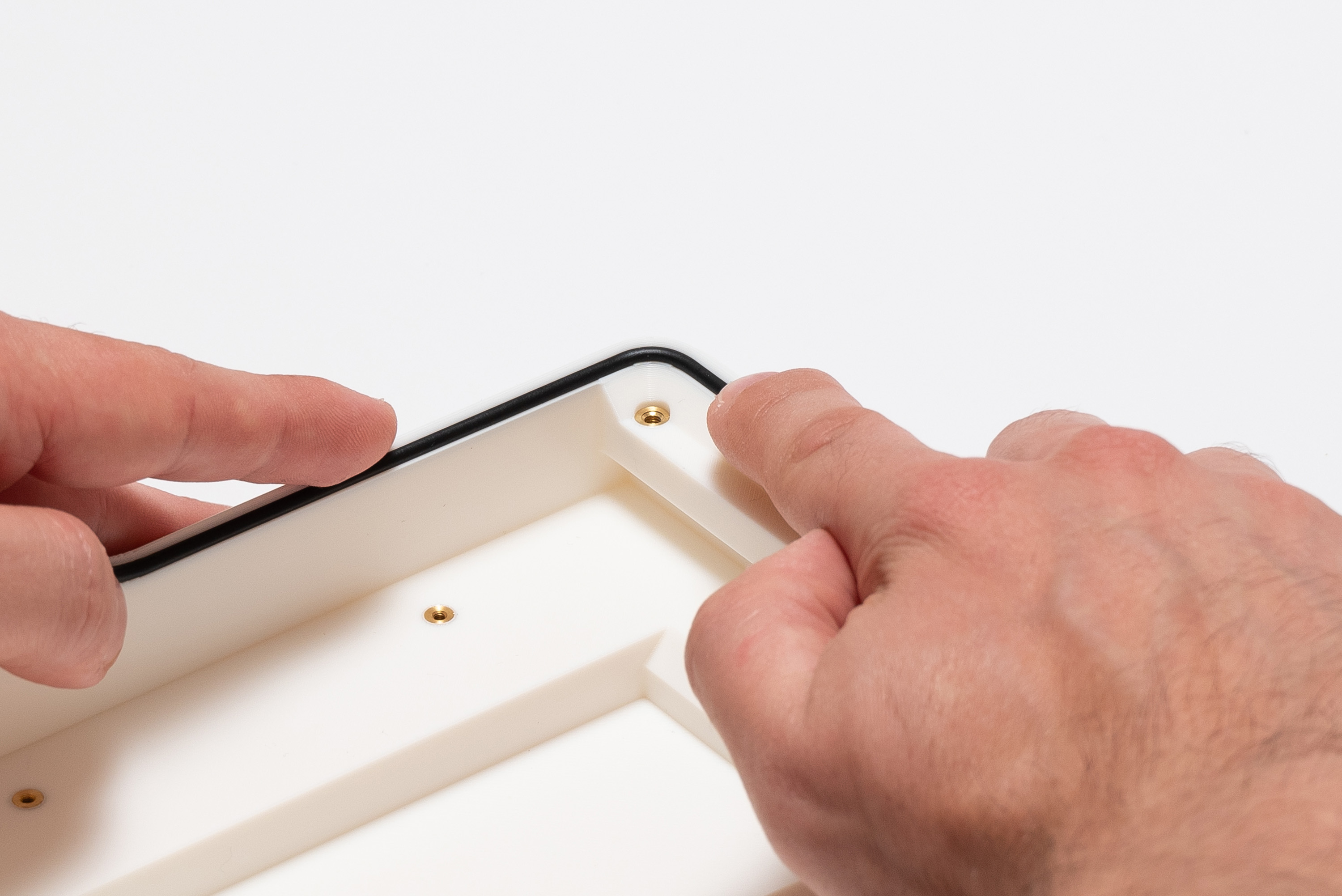
Align the tip of the cord to the recess on the top piece, then gently press it perpendicularly to fit inside:
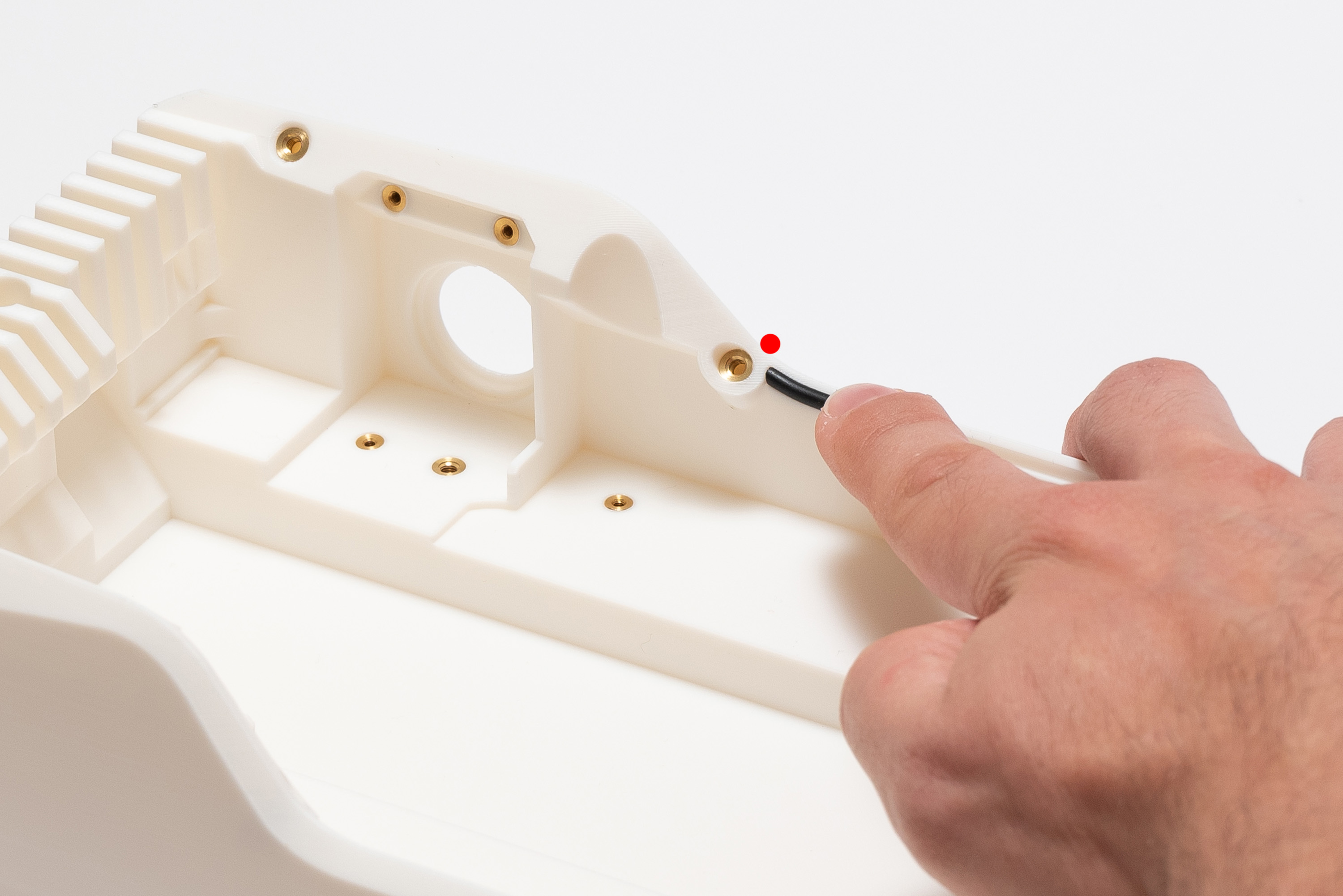
Without stretching, keep pressing until reaching the other extremity of the recess:
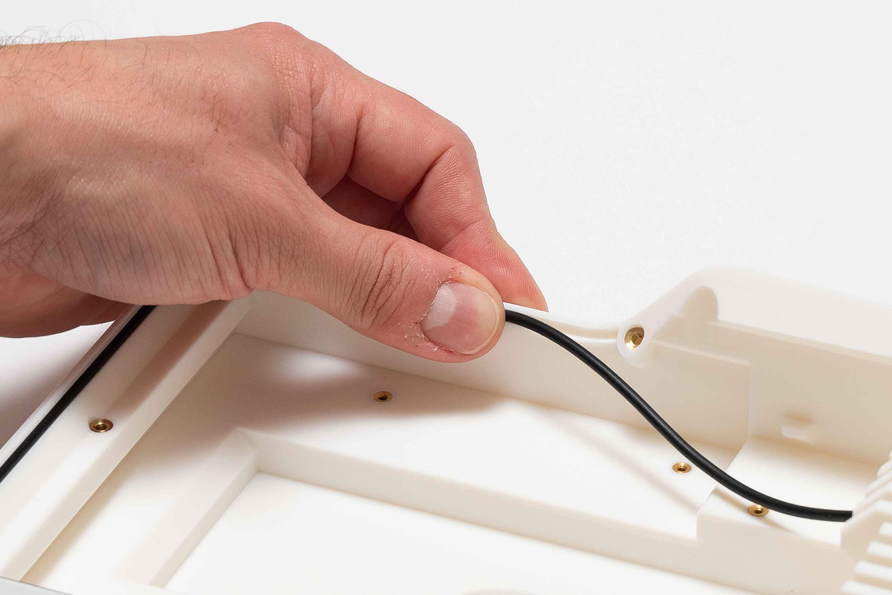
Cut the cord to match the extremity, and push it to finish:
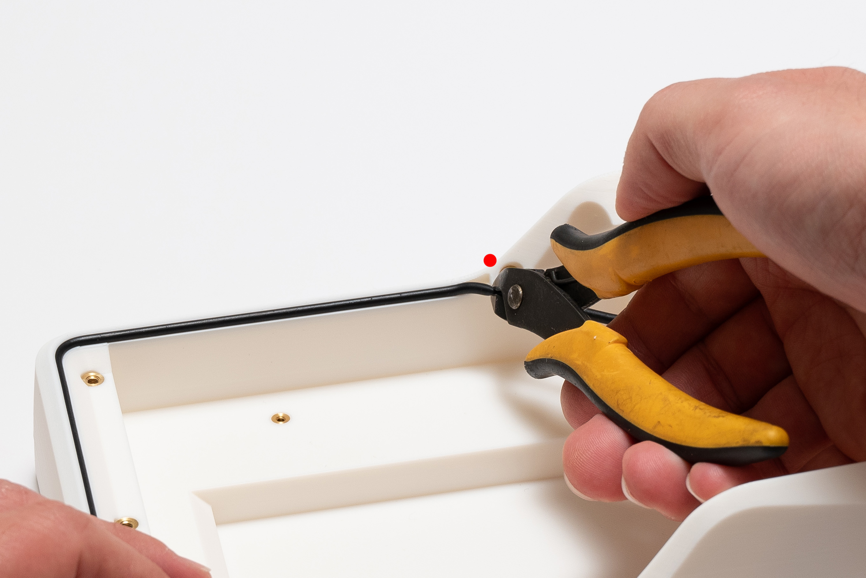
✅ Result
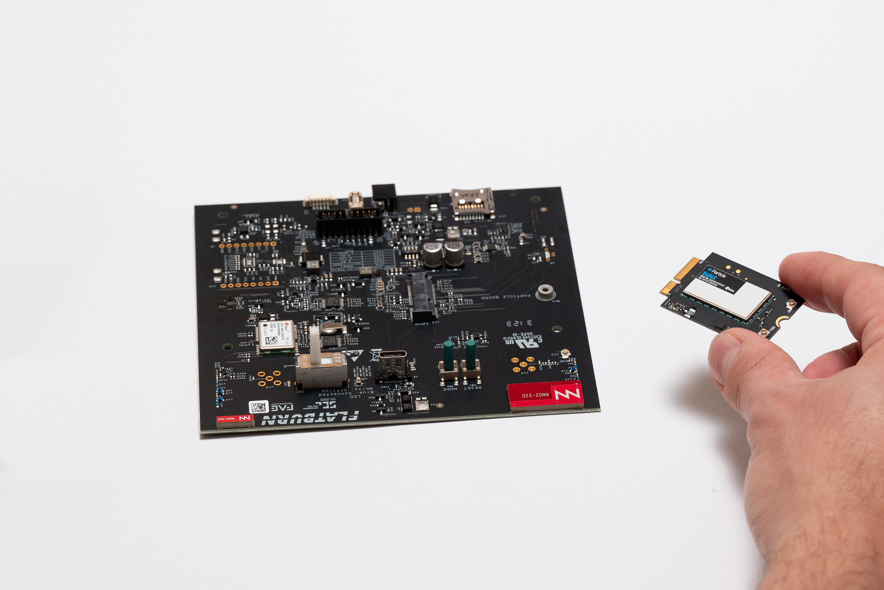
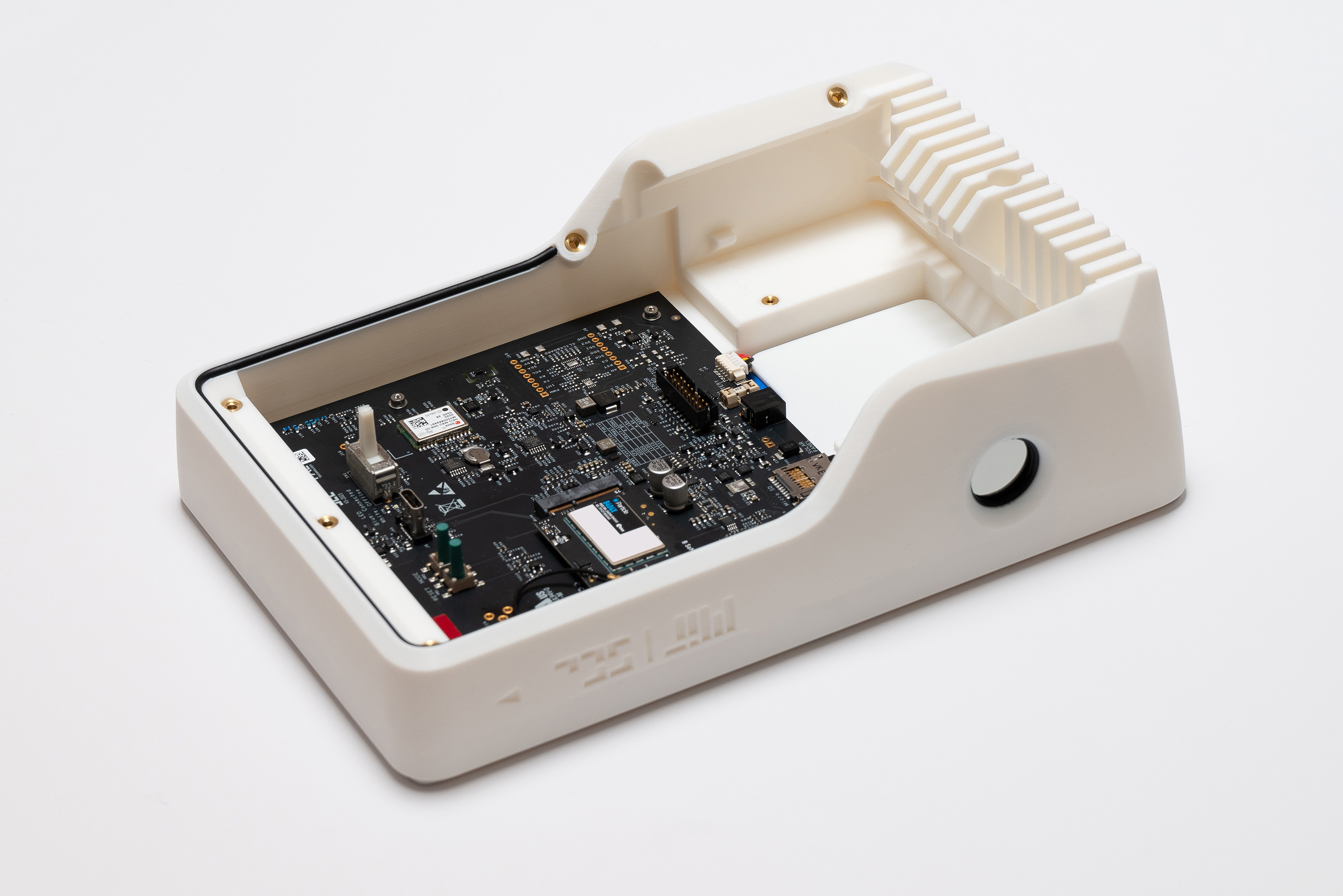
Step 7 – Populate Main Board
Remember to choose the type of Particle module (EMEA or US) according to where the device will be deployed.
More information here.
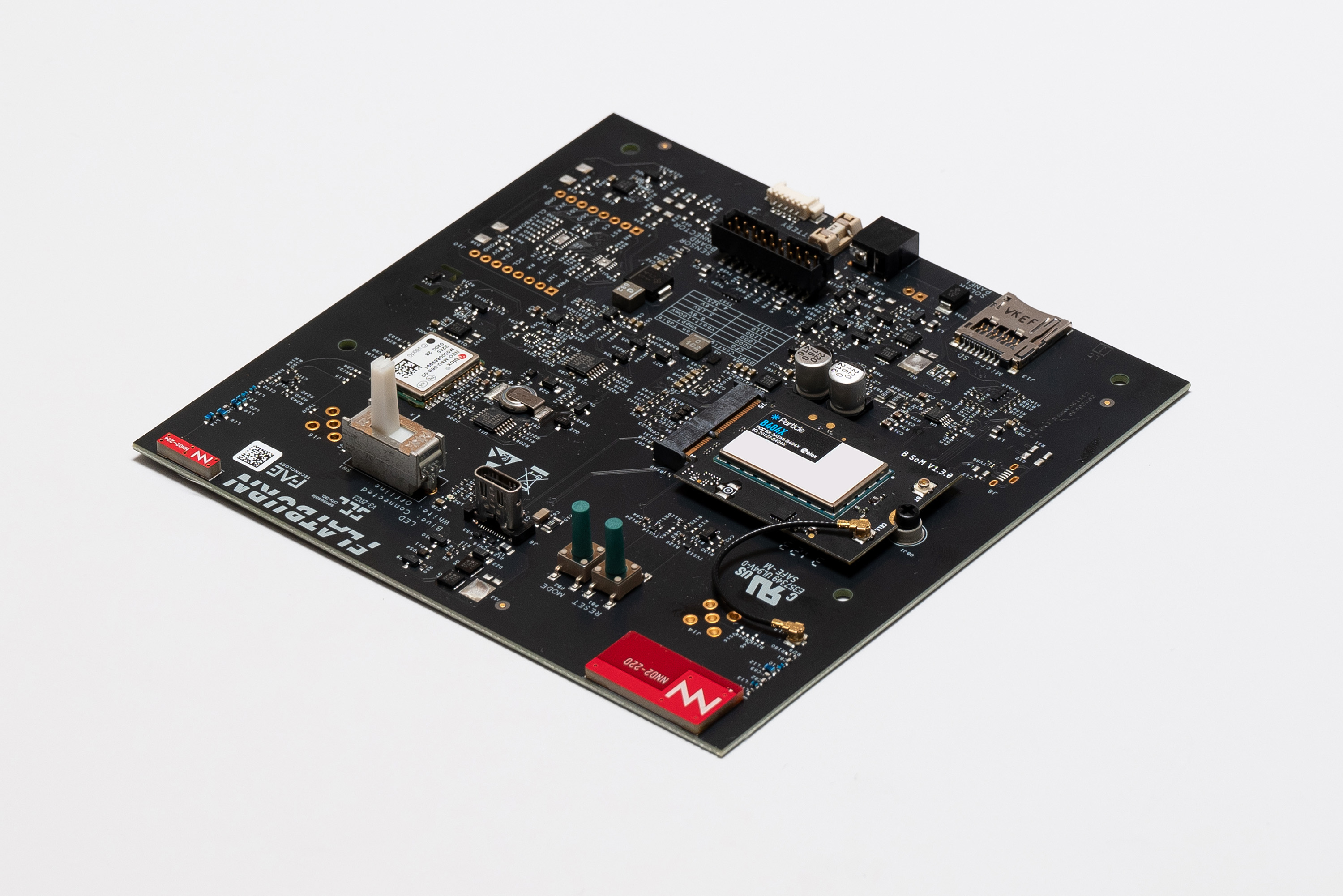
Insert the Particle module into the Main Board slot with its branding facing up:
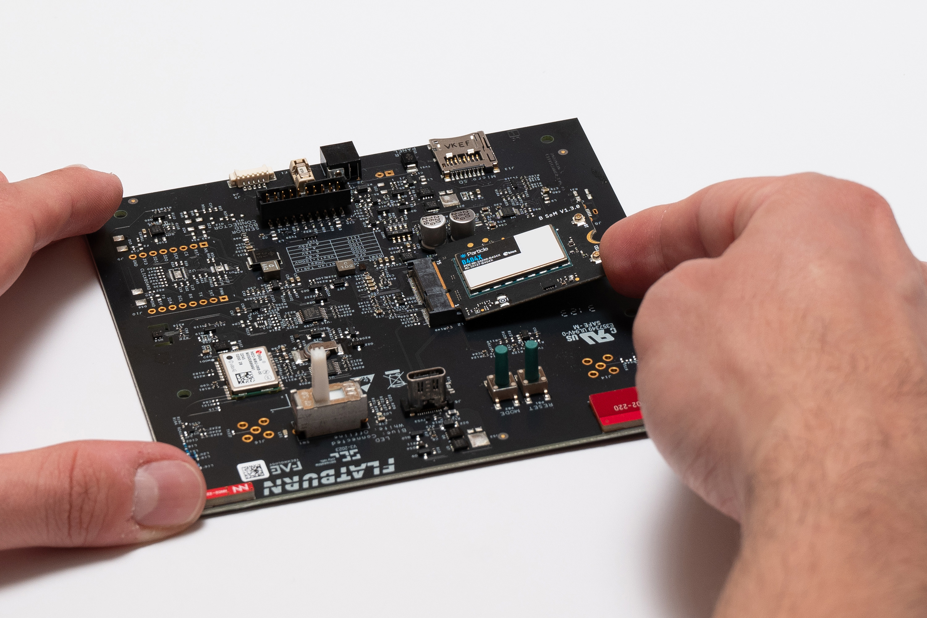
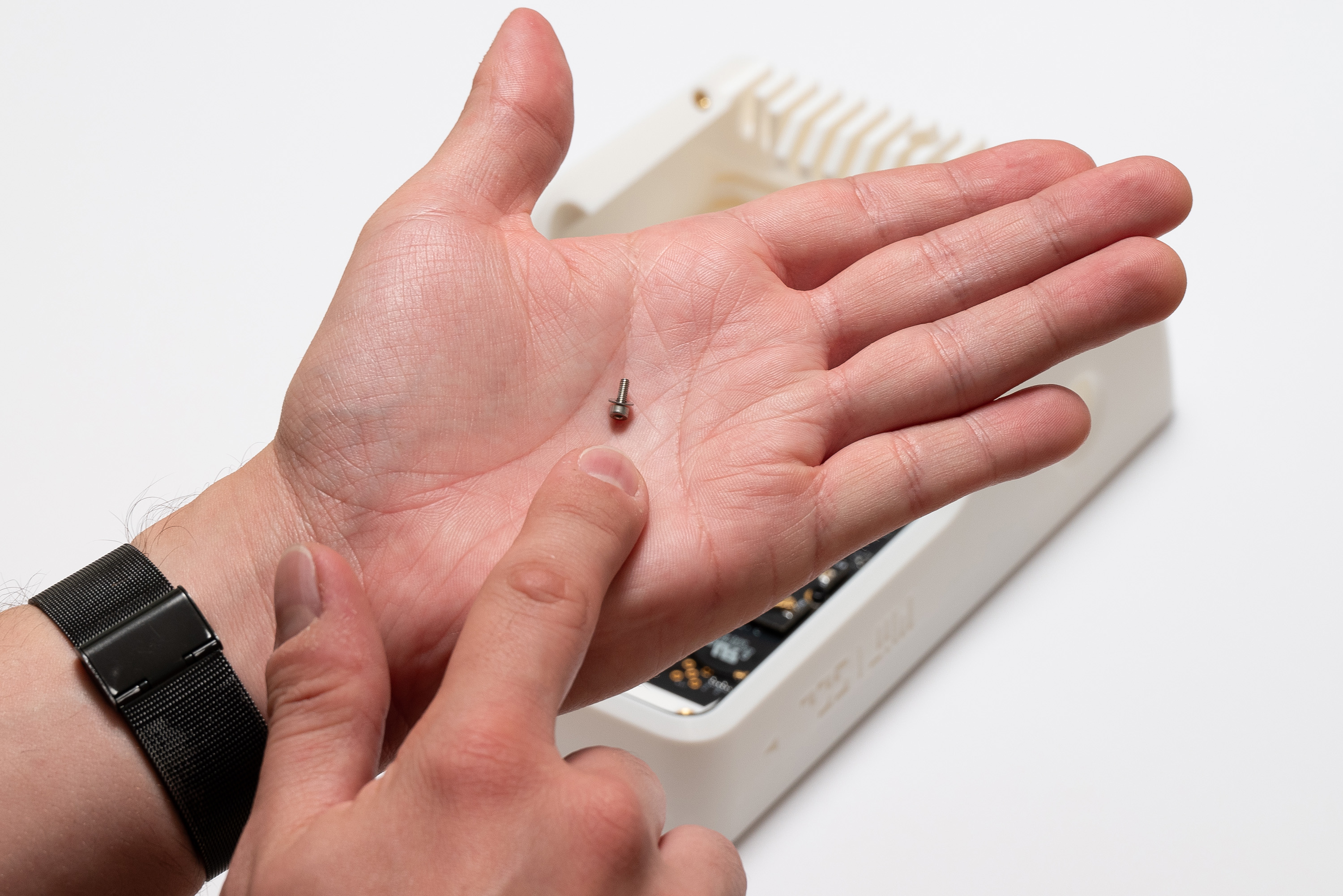
Fasten the only 1x M2.5x4 screw into the Main Board to secure the module:
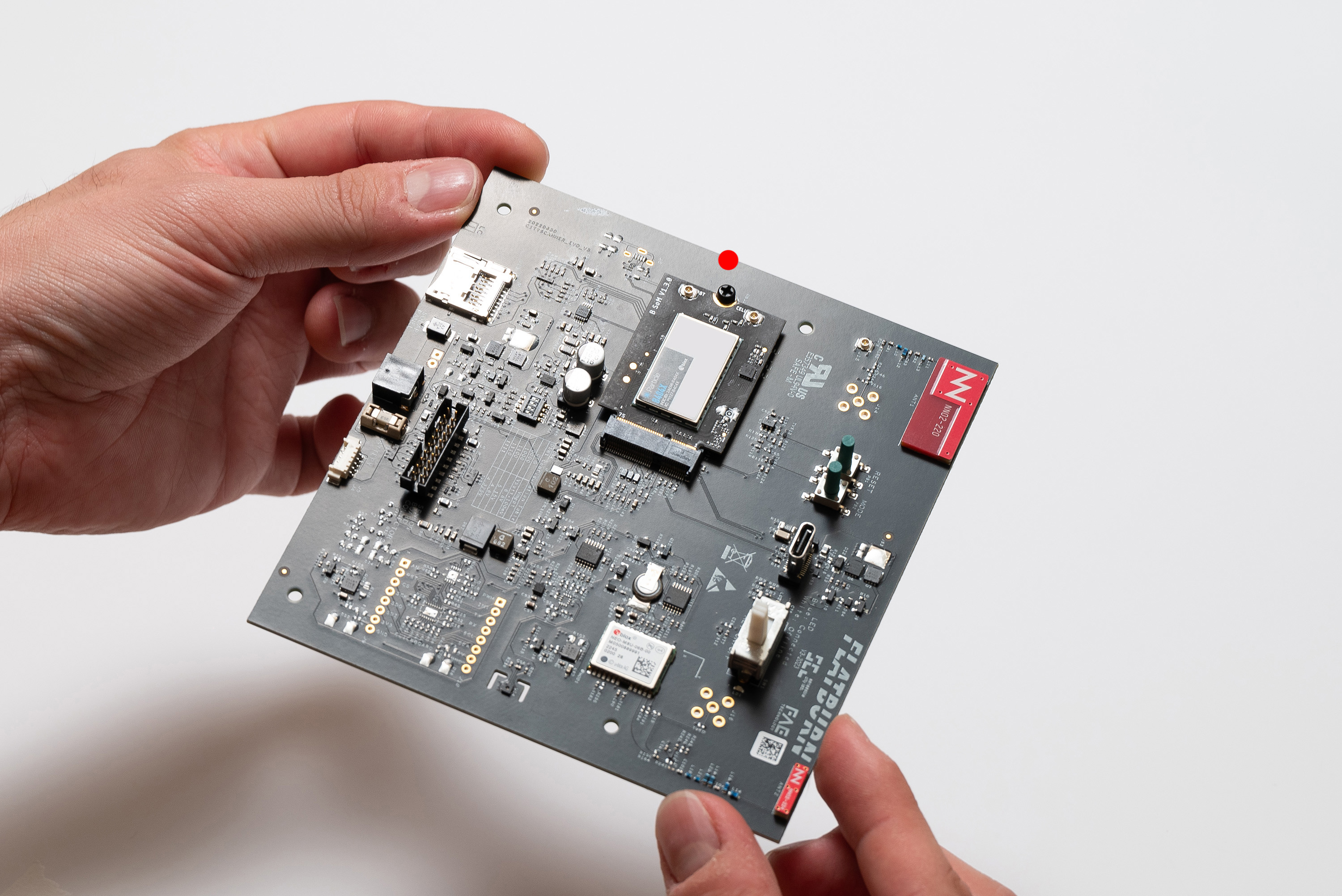
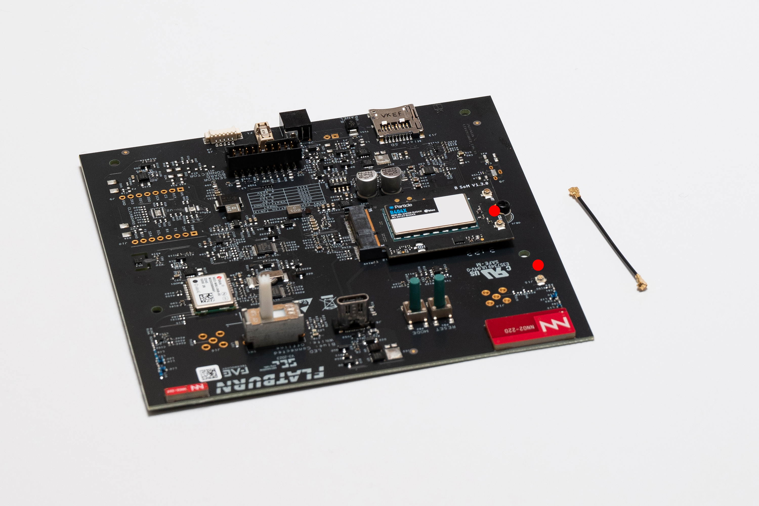
Now, pick the GSM antenna cable and connect it between the Particle module and the Main Board:
- Depending on the Particle module type, the antenna connector will be in different place (always signed with a CELL label).
- It can be tricky to snap the connector on. If needed, use a plier with care to not damage the connector and boards, pressing the connector from its front face, but never press from the sides because that will damage the connector.
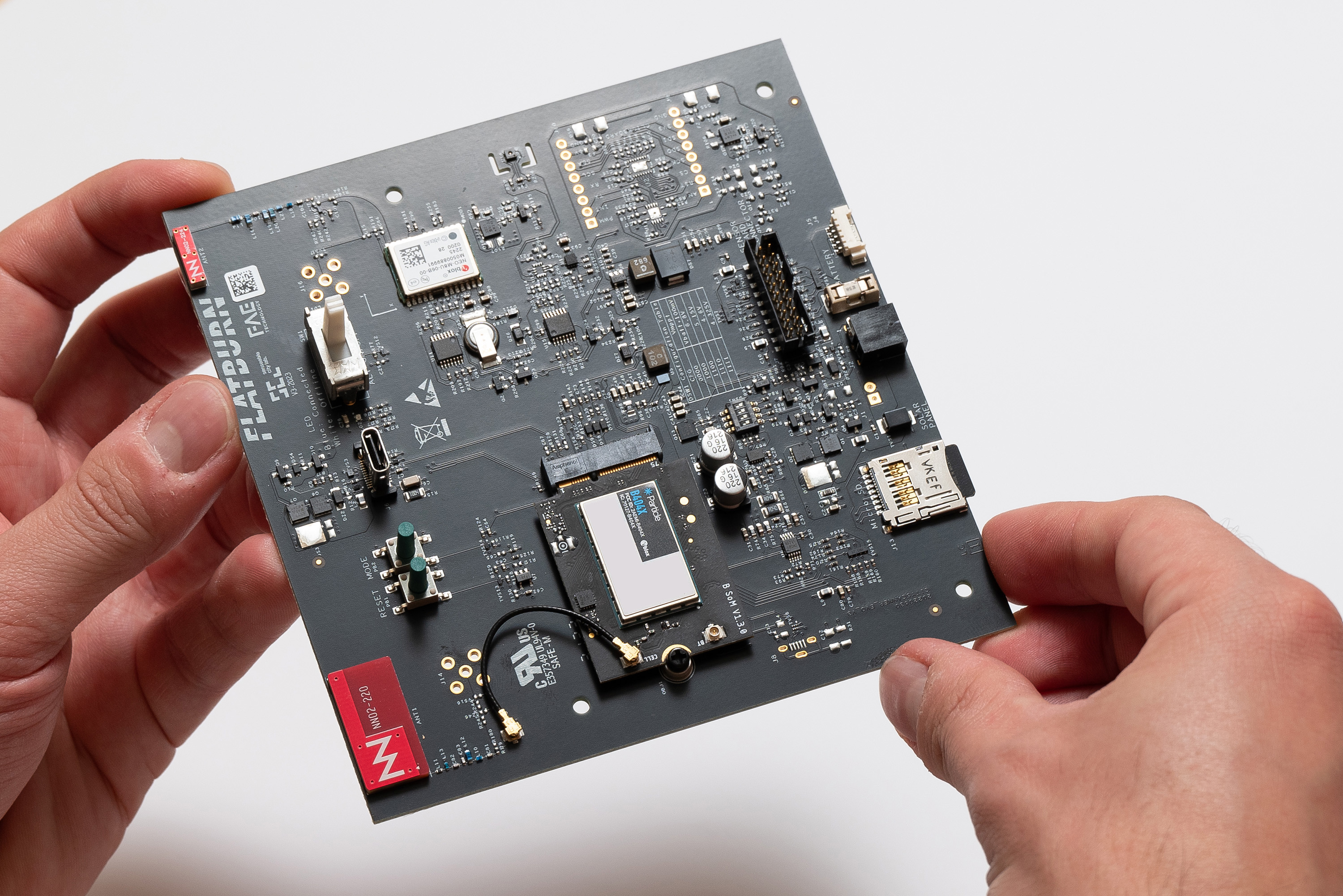
To finish, add the microSD card to the Main Board slot:
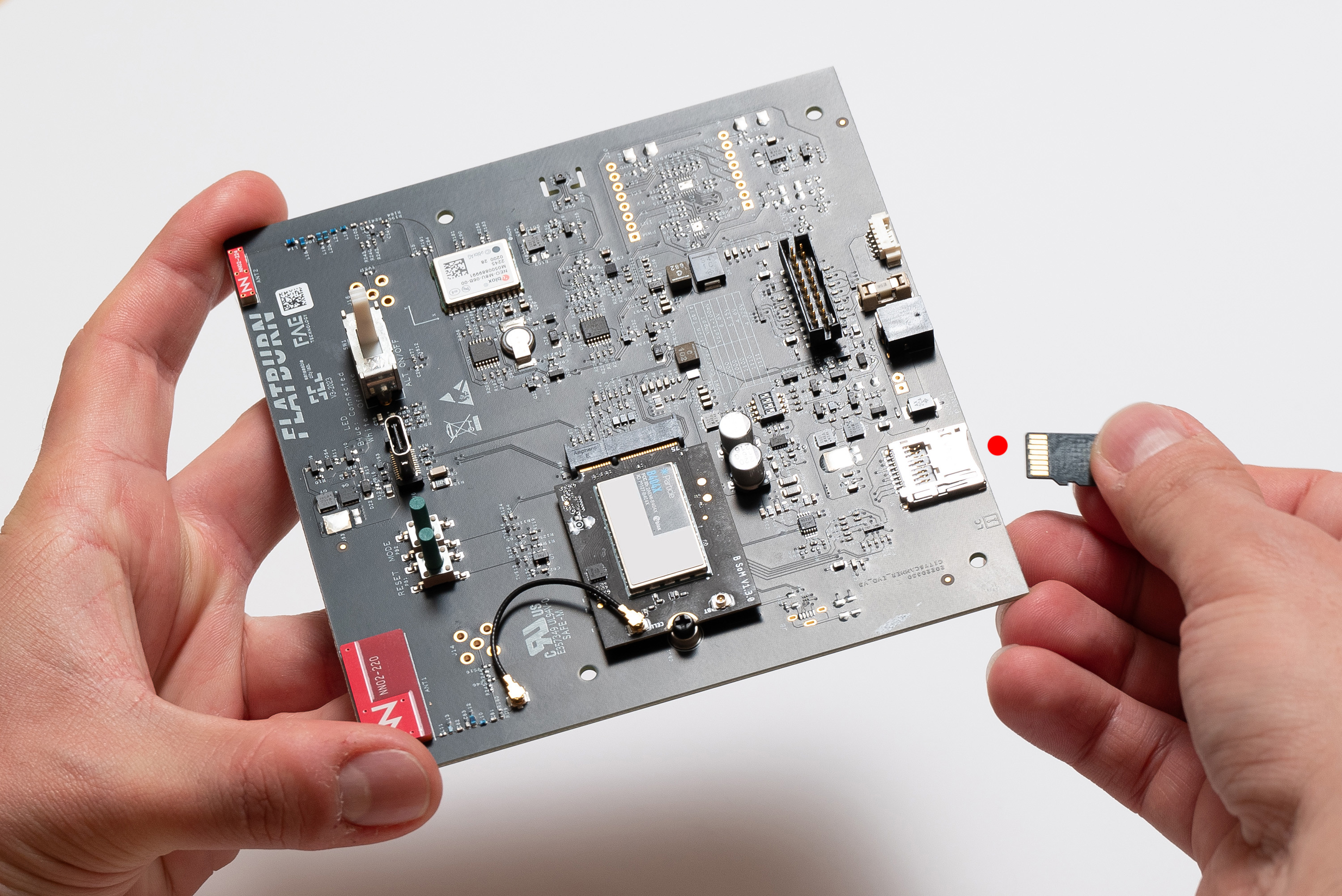
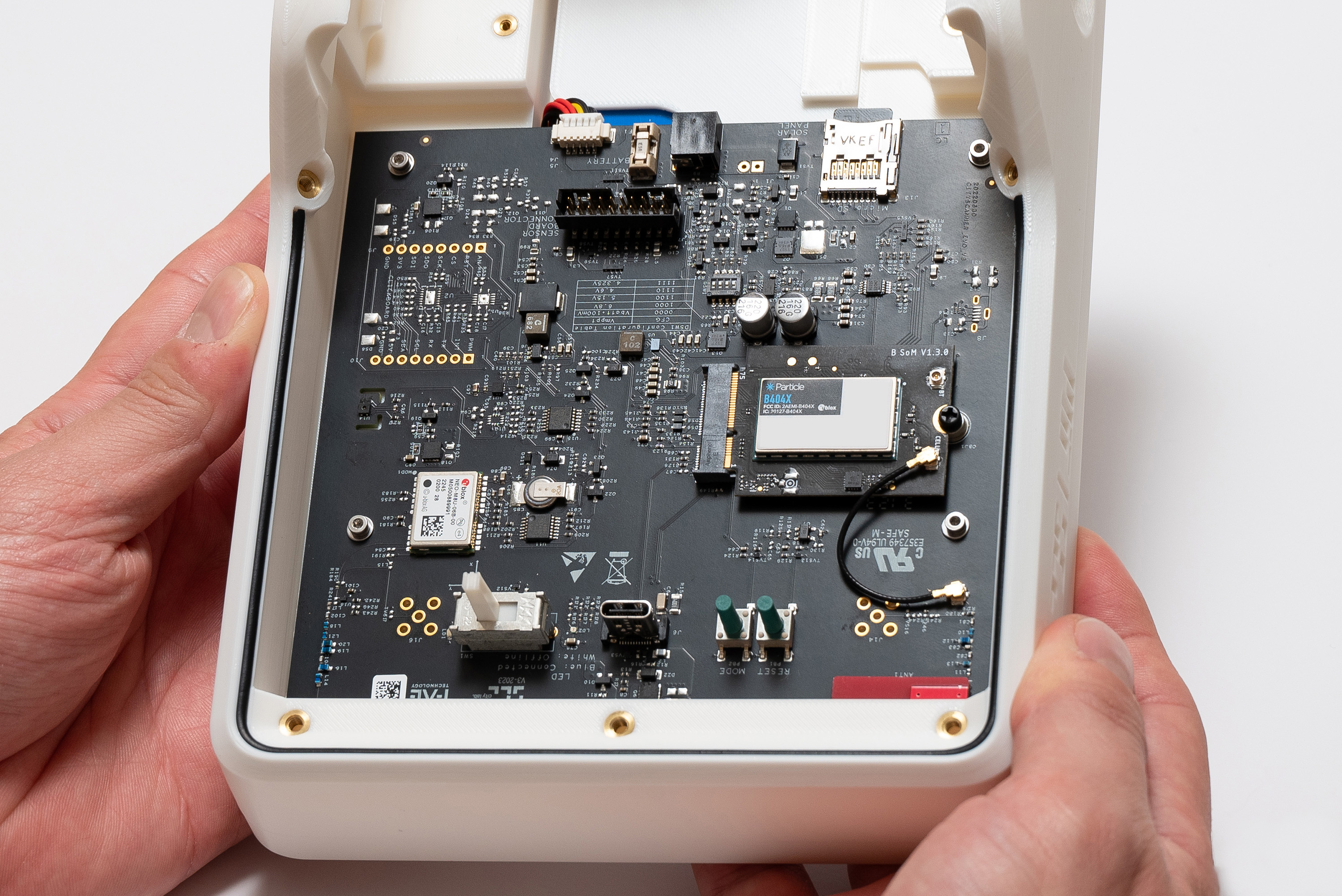
✅ Result
Step 8 – Battery and Main Board
Place the battery on the top piece, making sure the cable orientation follows the image:
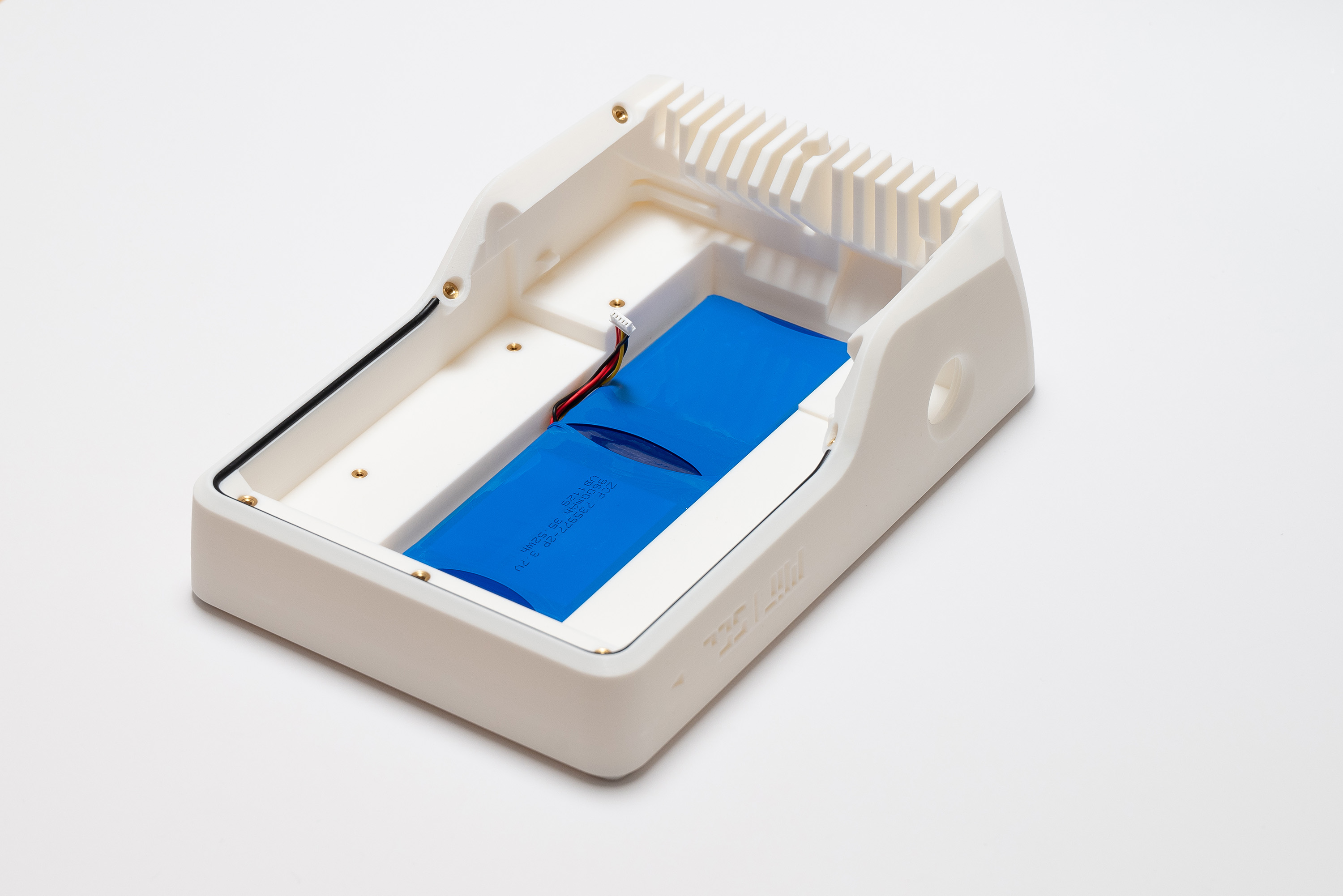
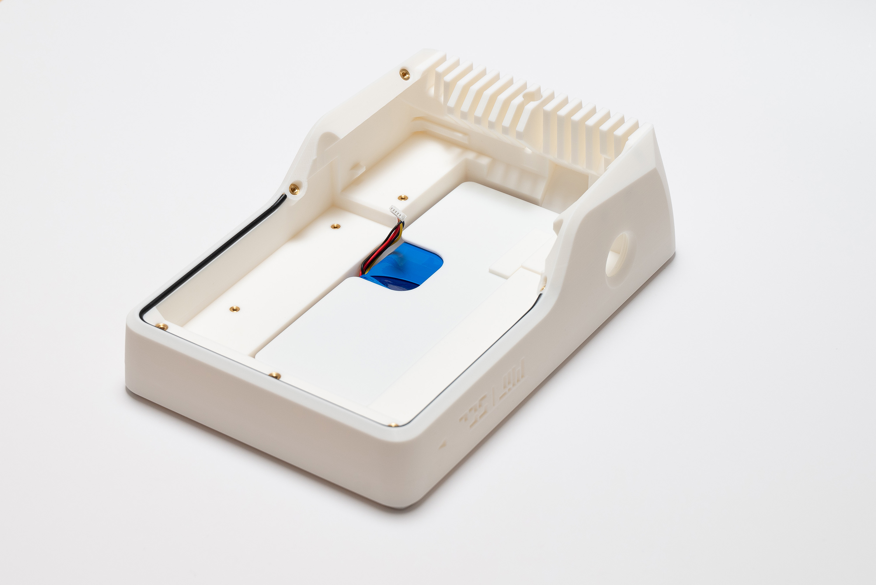
Then, add the battery_cover:
Now, pick the Main Board and connect the battery cable:
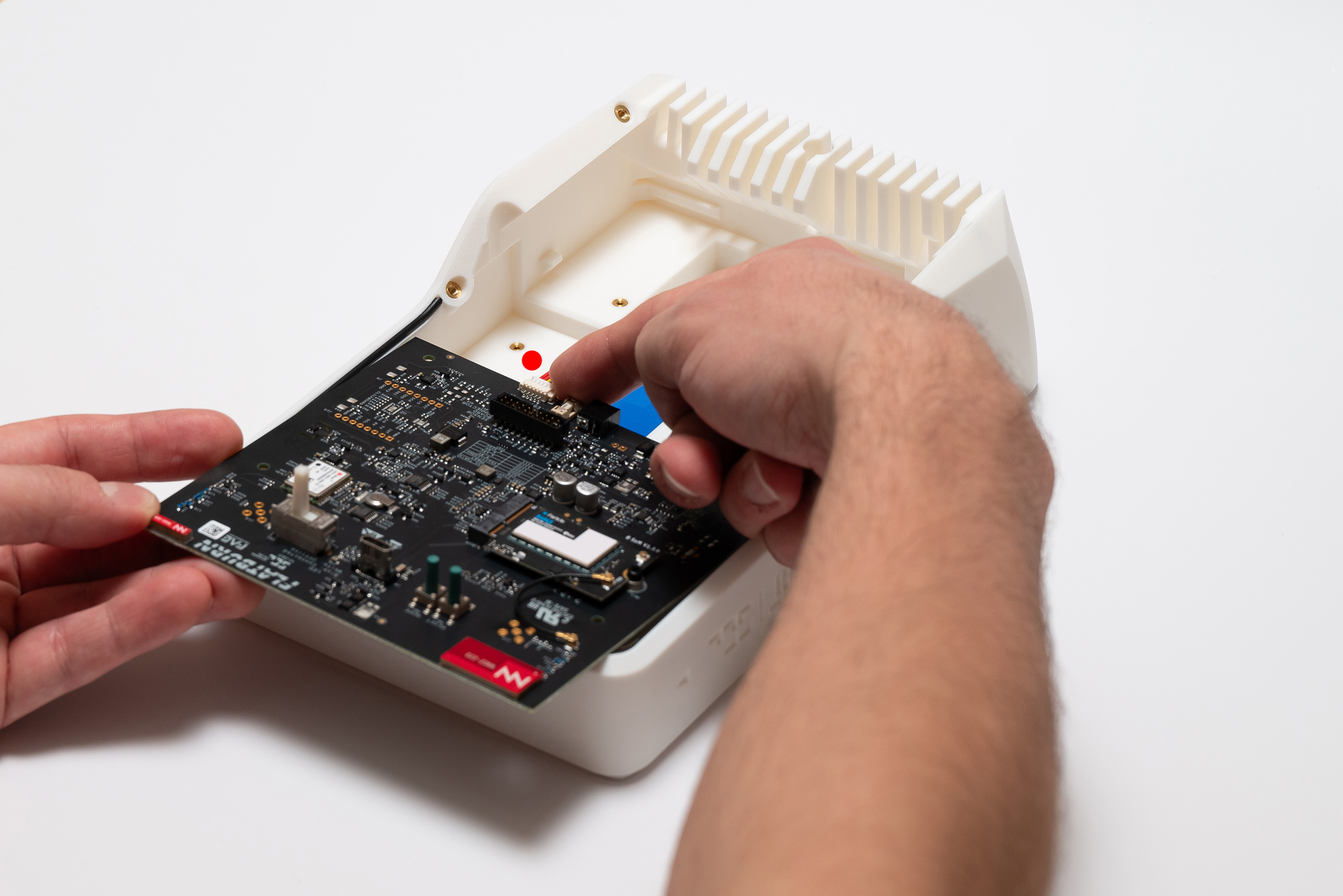
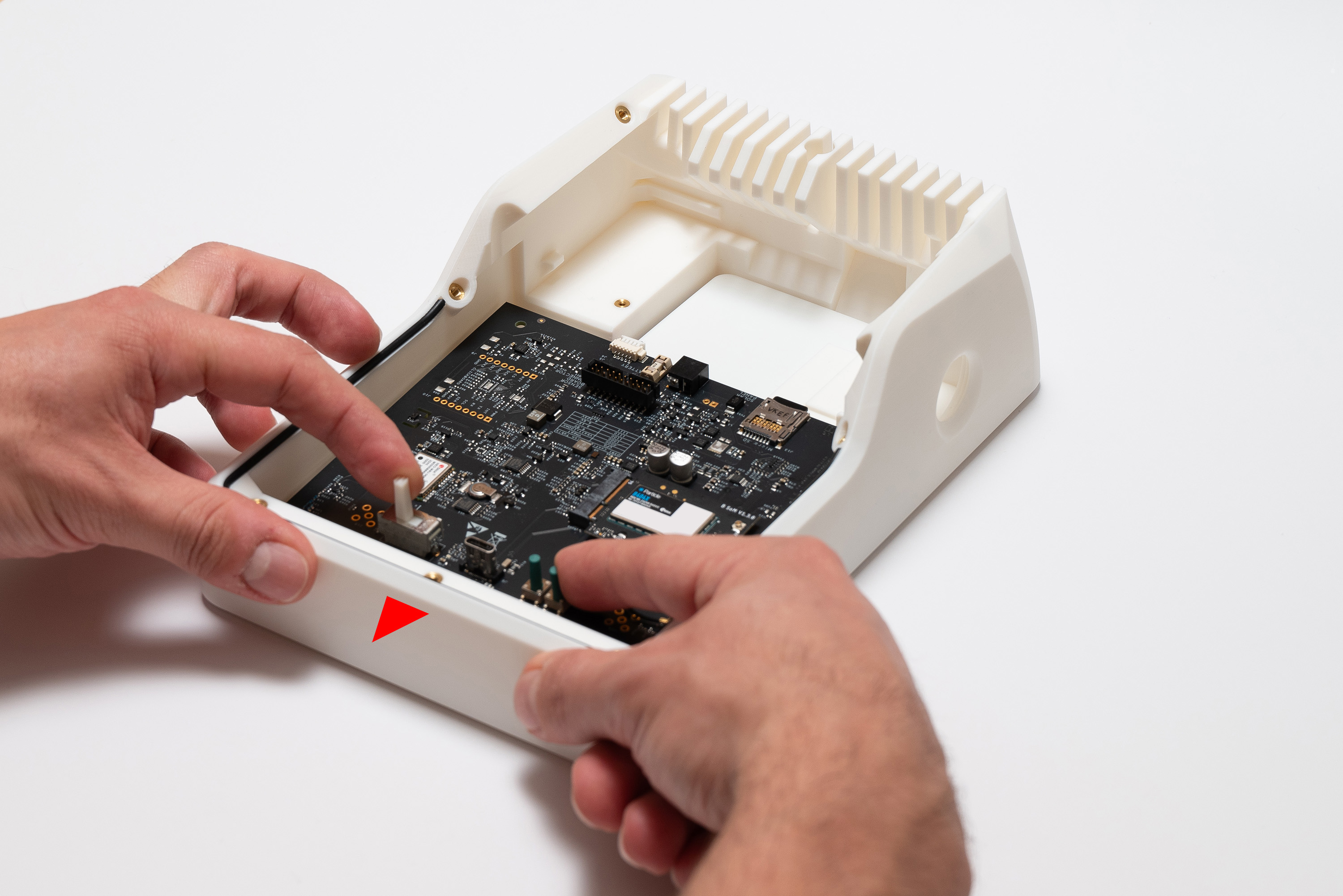
To insert the Main Board into the top piece, first place its front edge against the top piece at an angle:
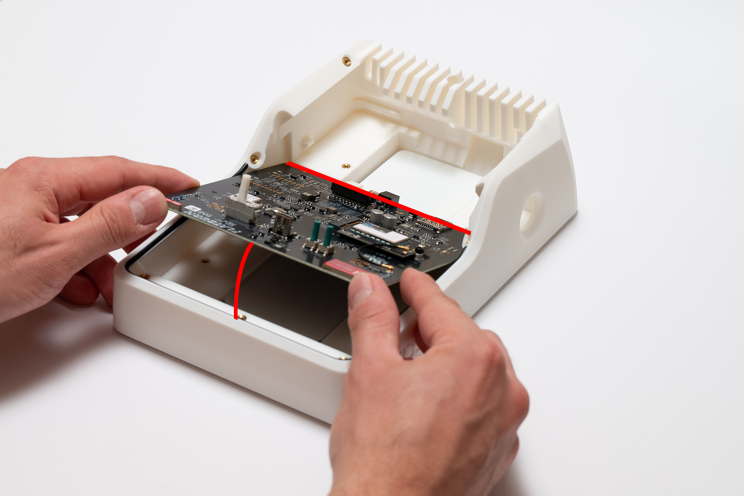
Finally, lower and then slide it back:
Step 9 – Secure Main Board
For fixing the Main Board, pick 4x M2 washers and put each into 4x M2X6 screws
Fasten them into the four indicated holes:
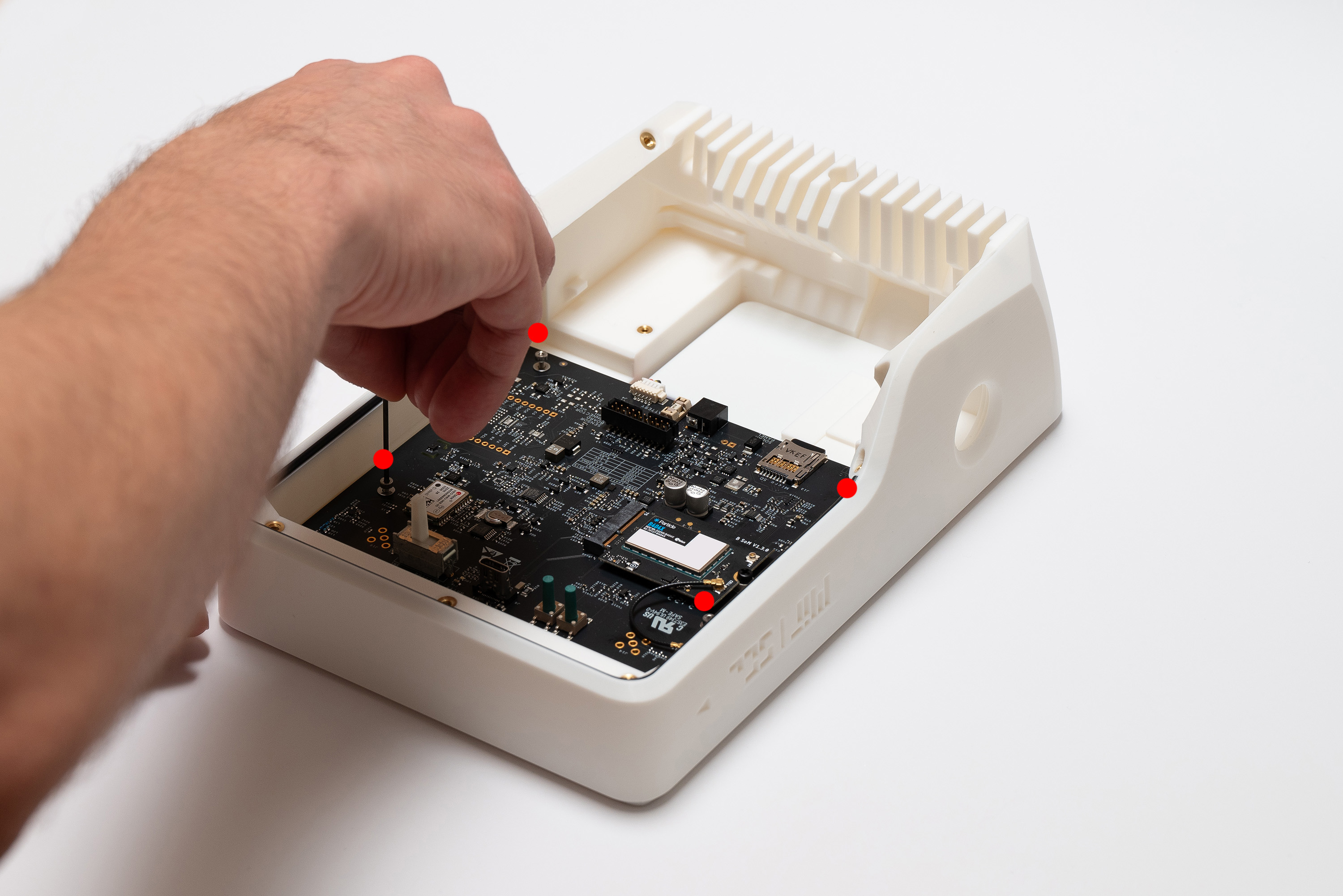
✅ Result
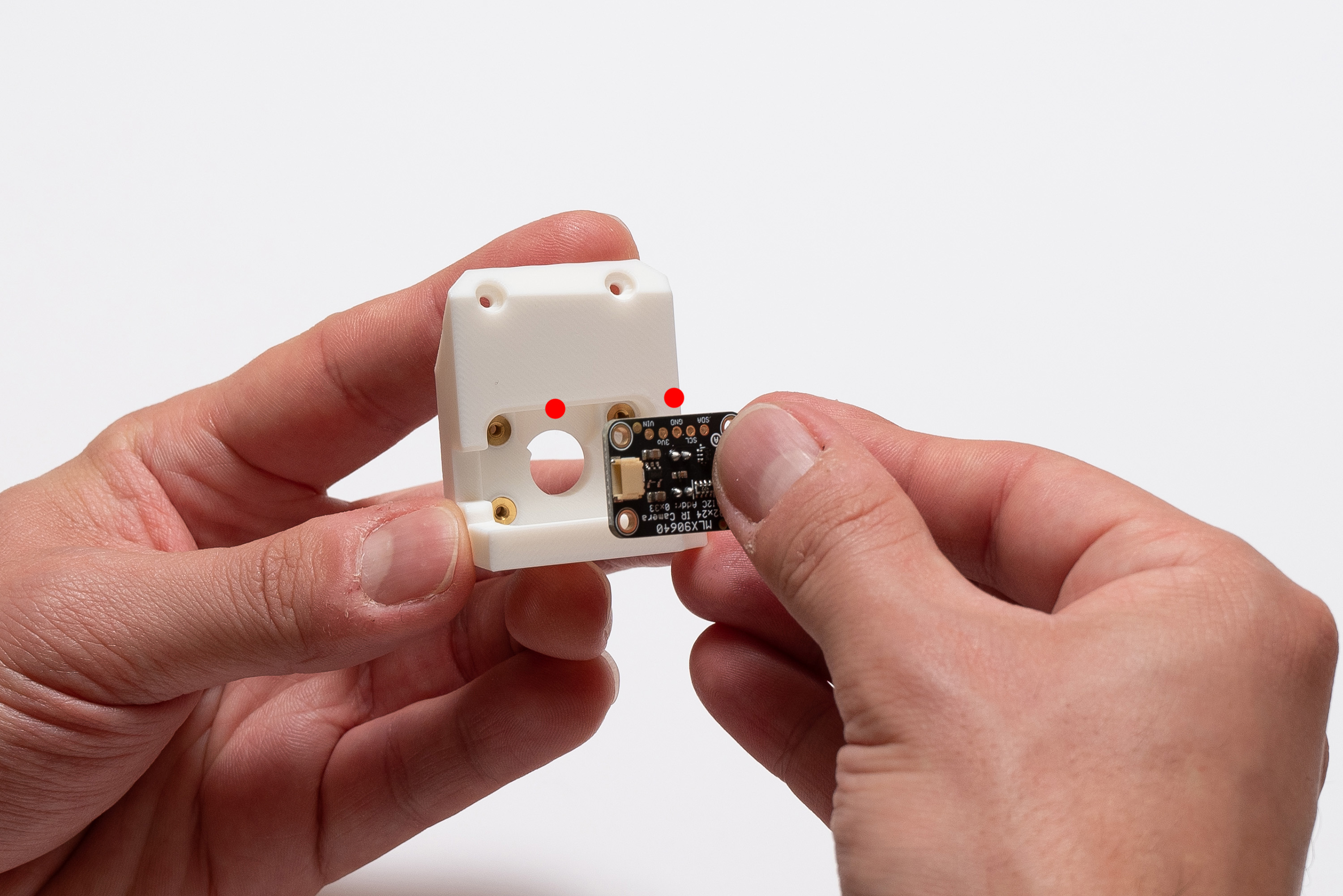
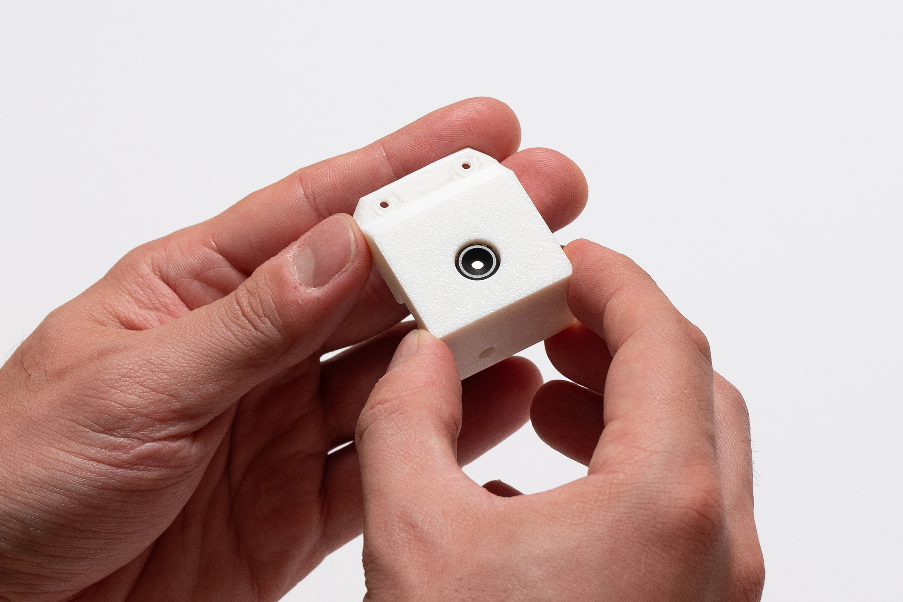
Step 10 – Thermal Camera
Be careful to not touch or scratch the lens (reflective circle inside the black cylinder).
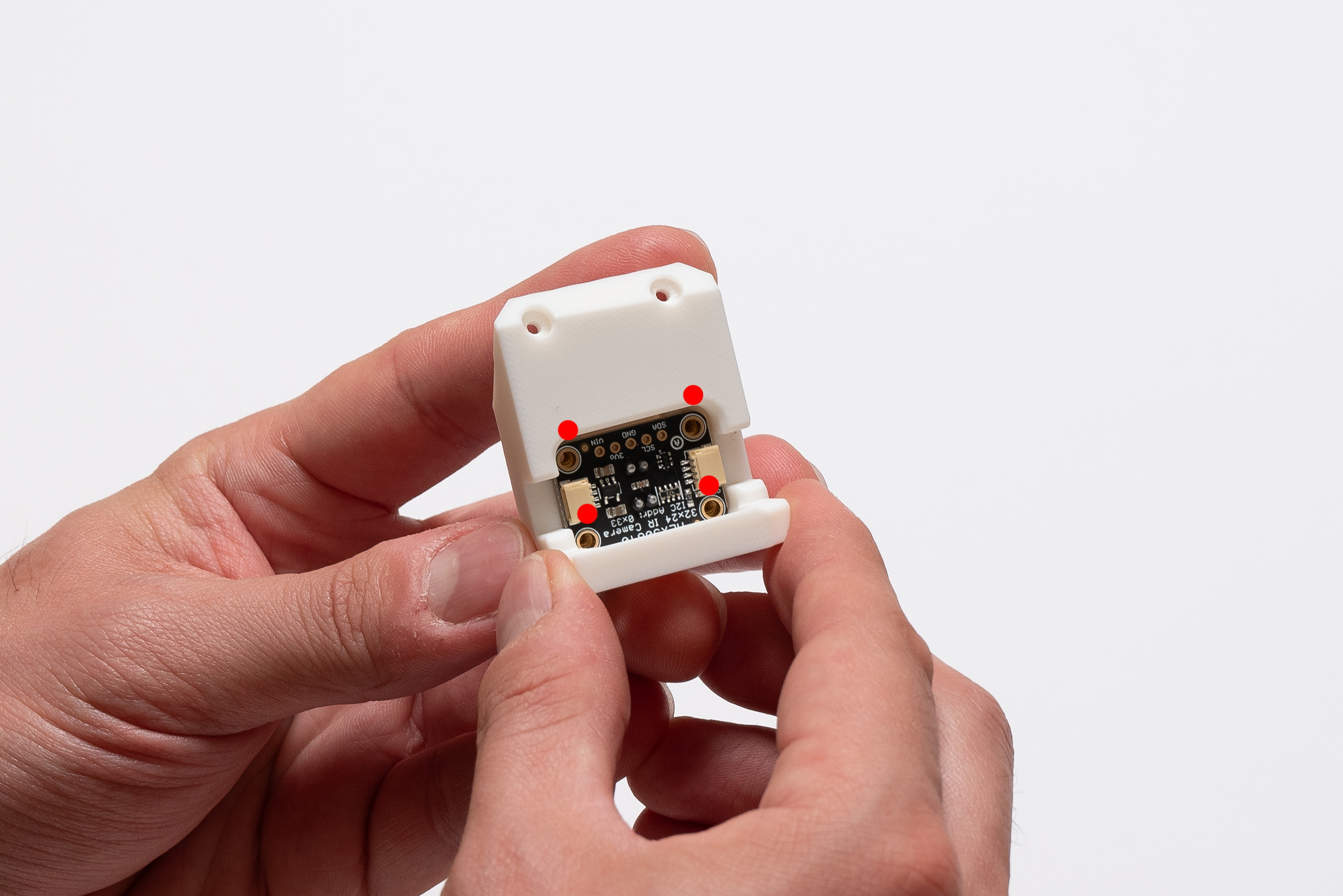
Start by placing the MLX9640 module into the camera piece while paying attention to the correct orientation on the image:
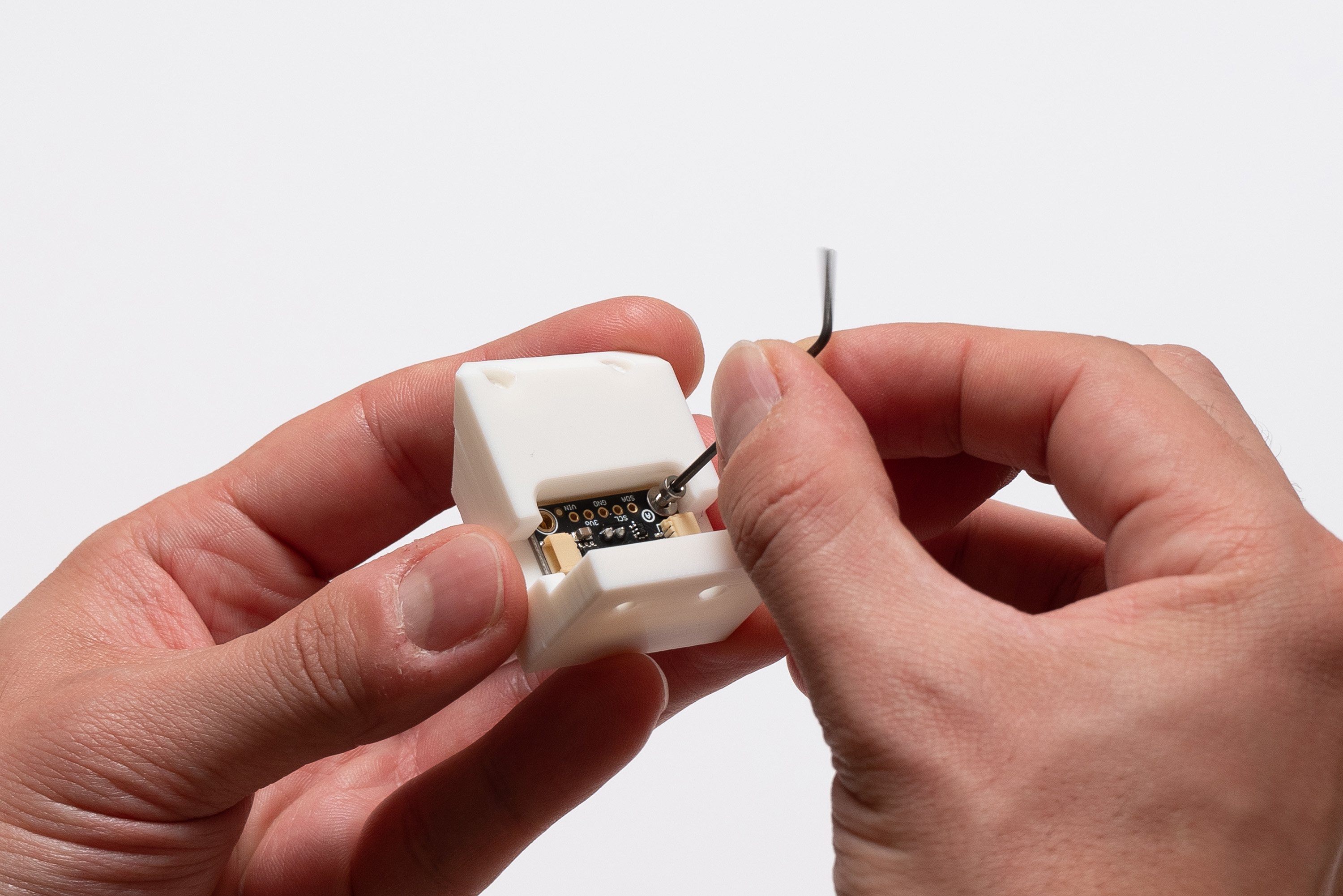
Now, combine 4x M2X6 screws with 4x M2 washers and place them into the four indicated spots:
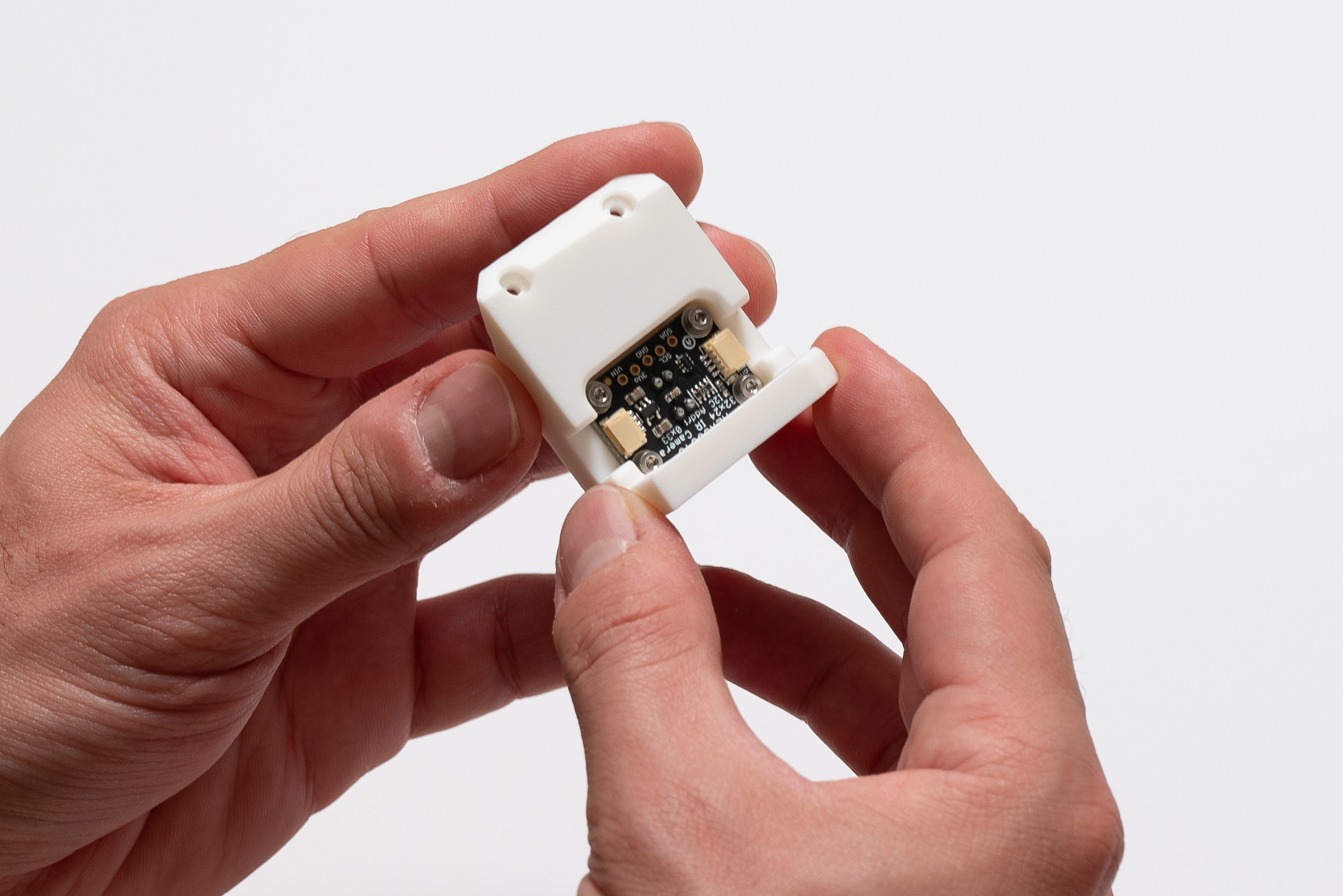
✅ Result
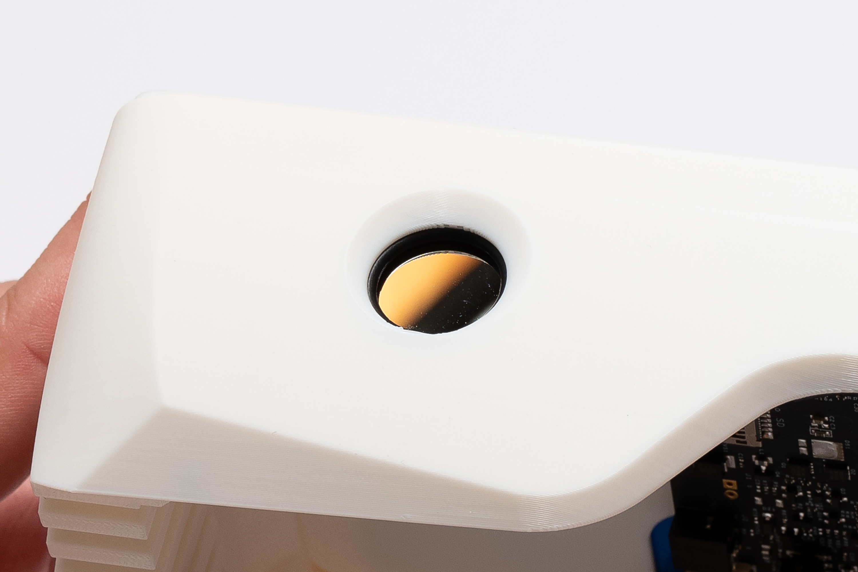
To install the camera module, start by placing the O-ring inside the top piece, making sure it is well aligned to the receptacle:
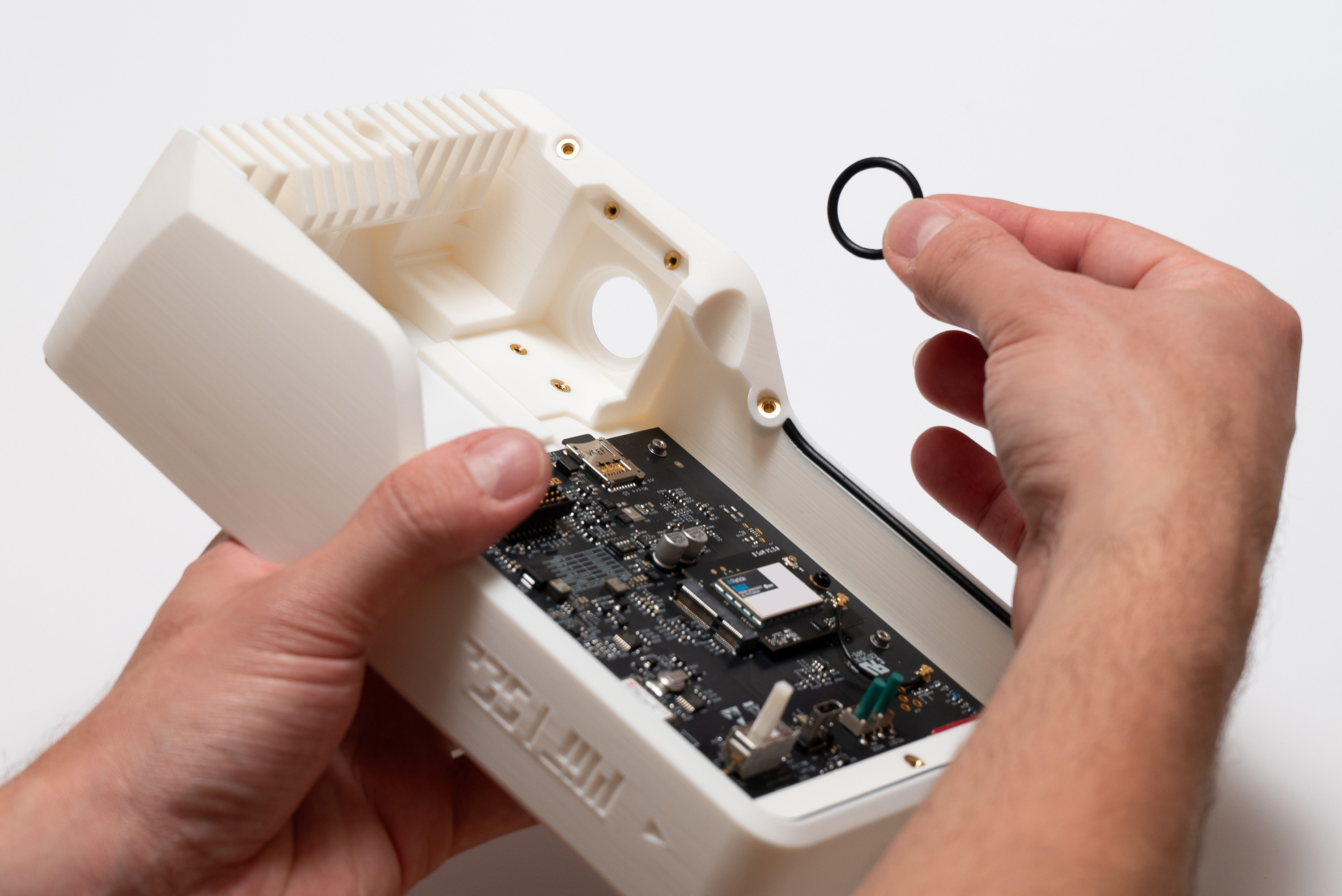
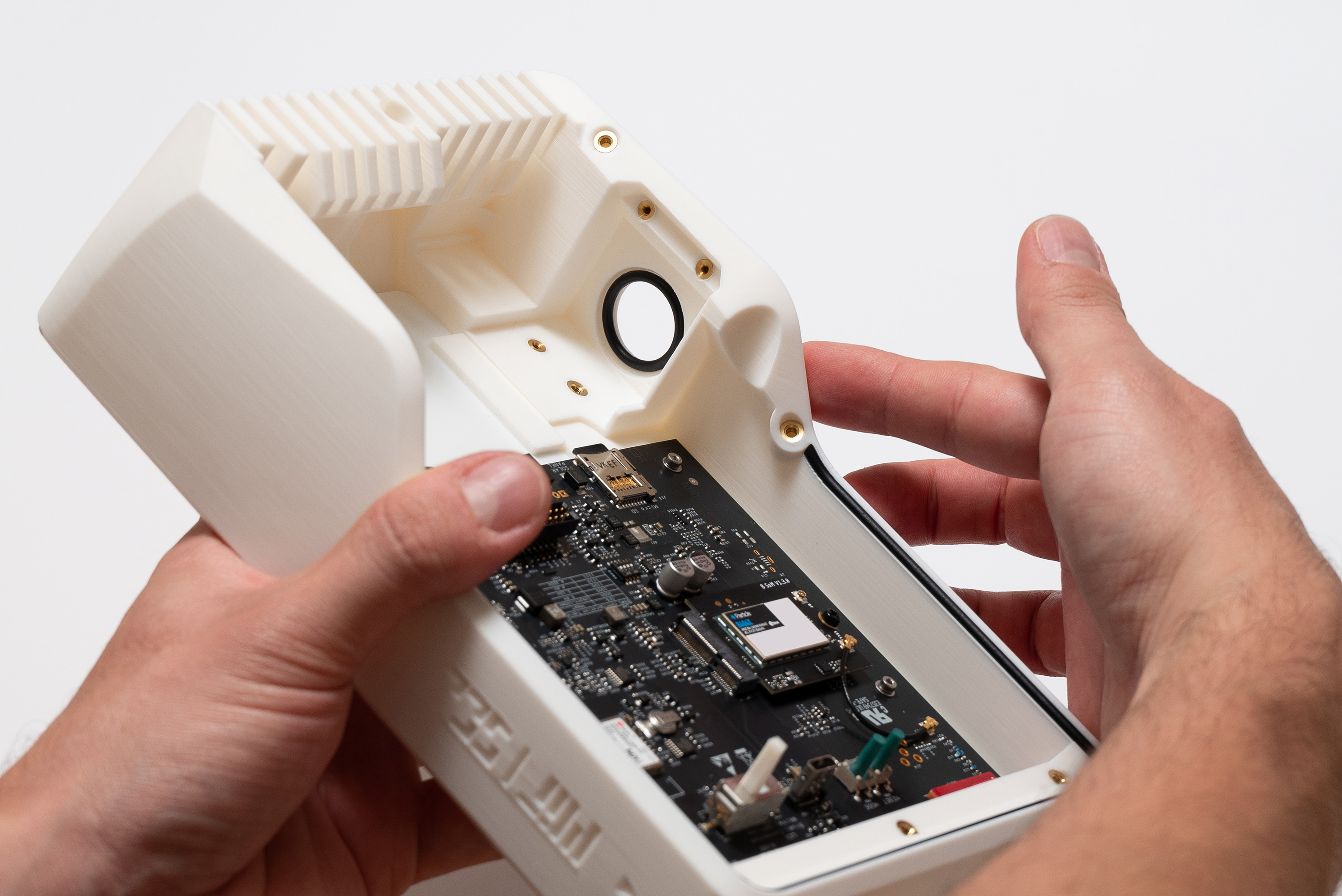
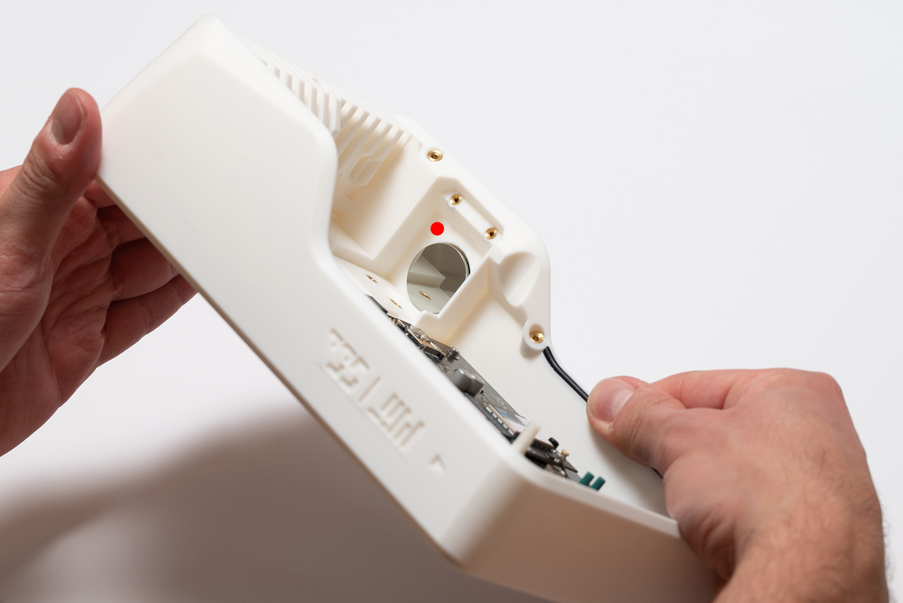
Then, tilt the device and very carefully place the germanium lens on top of the O-ring by holding it by its edges.
It will be intentionally loose, because there will be pressure between the germanium lens, the O-ring and the top piece to make the set watertight after securing the module.
Do not touch any of the faces of the germanium lens because it will compromise its imaging performance.
If you accidentally do so, please clean it with a microfiber cloth immediatelly.
Take advantage of the already angled device to slide the camera module in, and then hold it steadily in place while inserting 1x M2x6 screw into the left hole (the front is reserved for an M3 screw that will be used later)
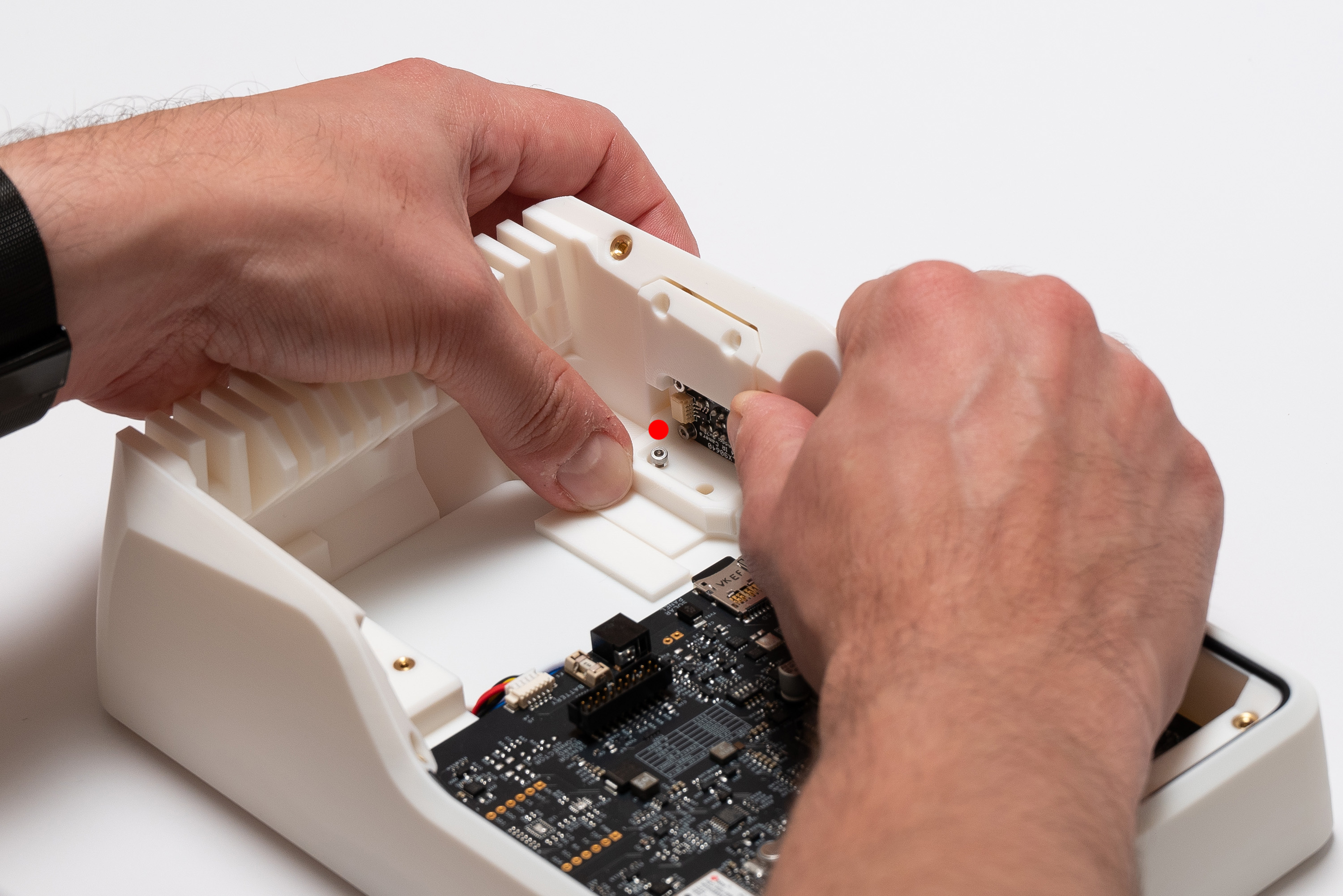
Keep holding the module while fastening the screw:
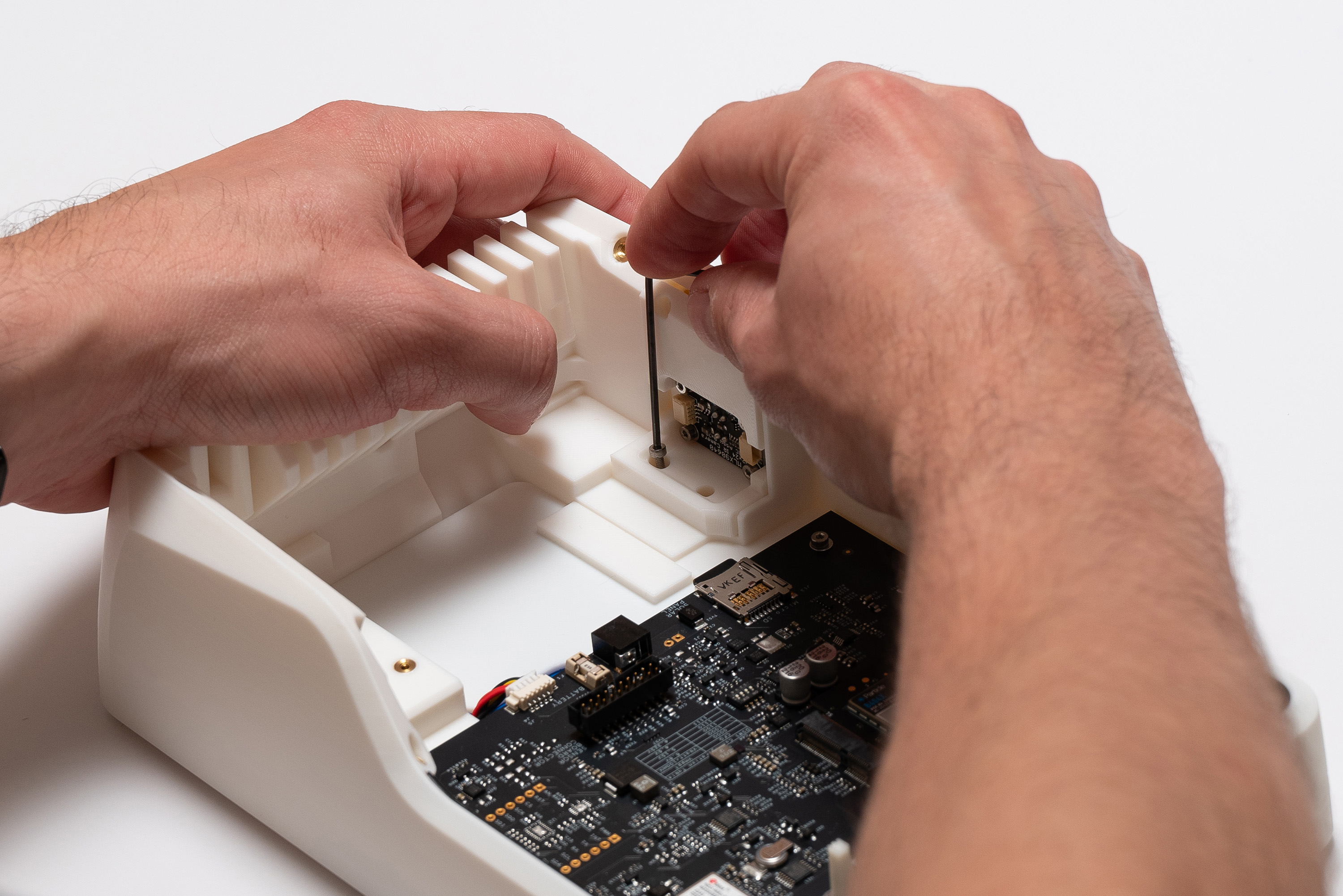
Now, fasten 2x M2x6 screws on the superior area.
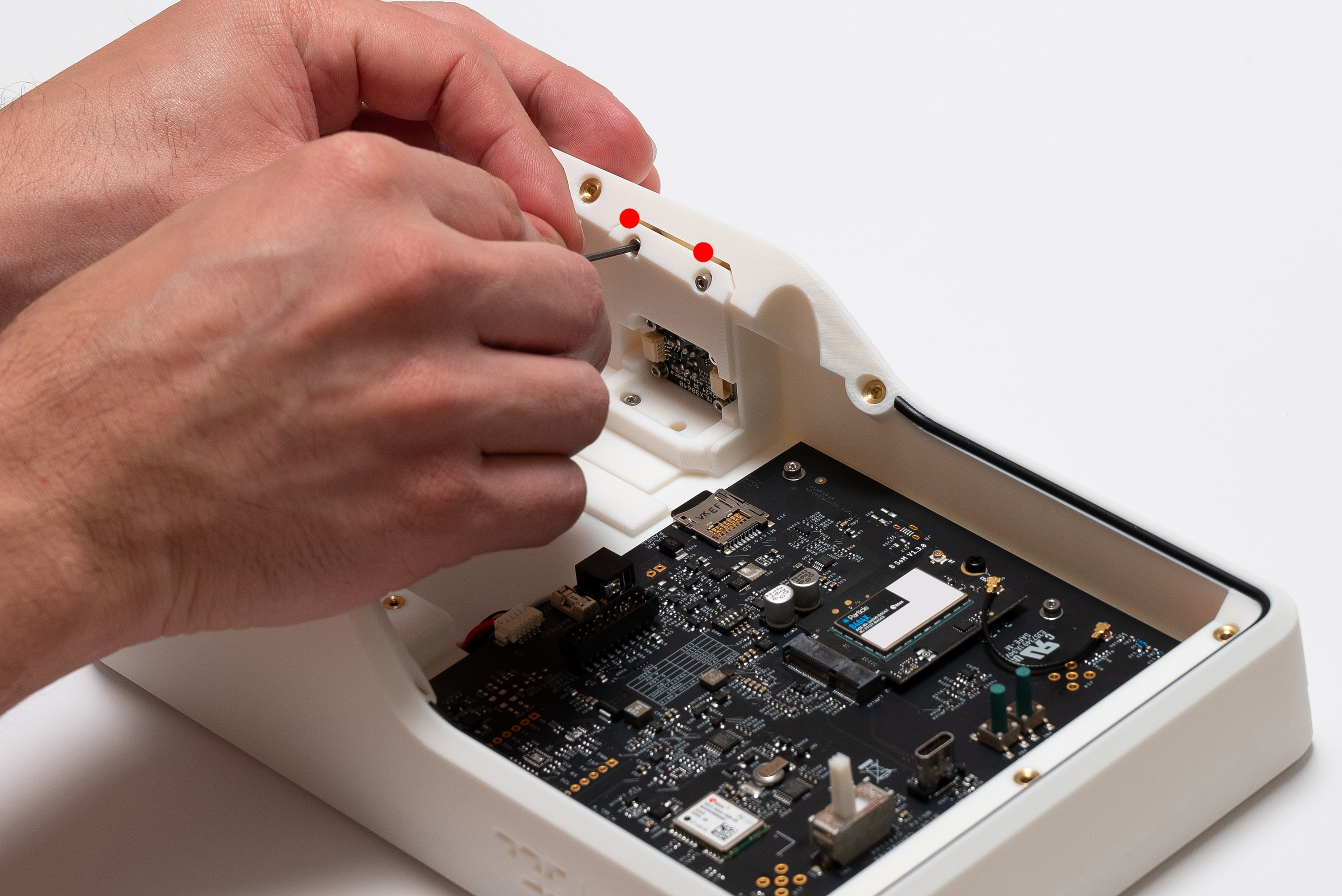
✅ Result
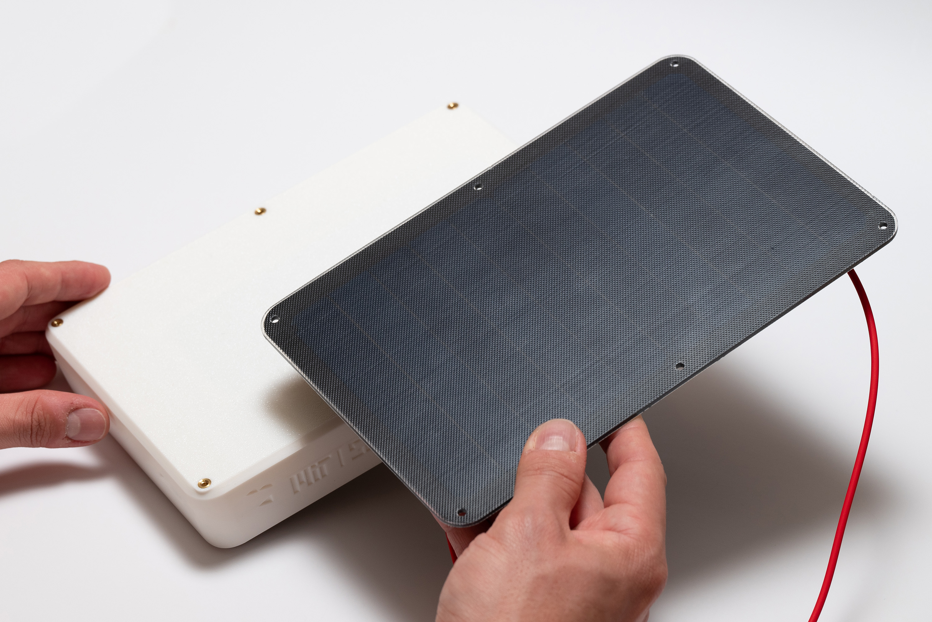
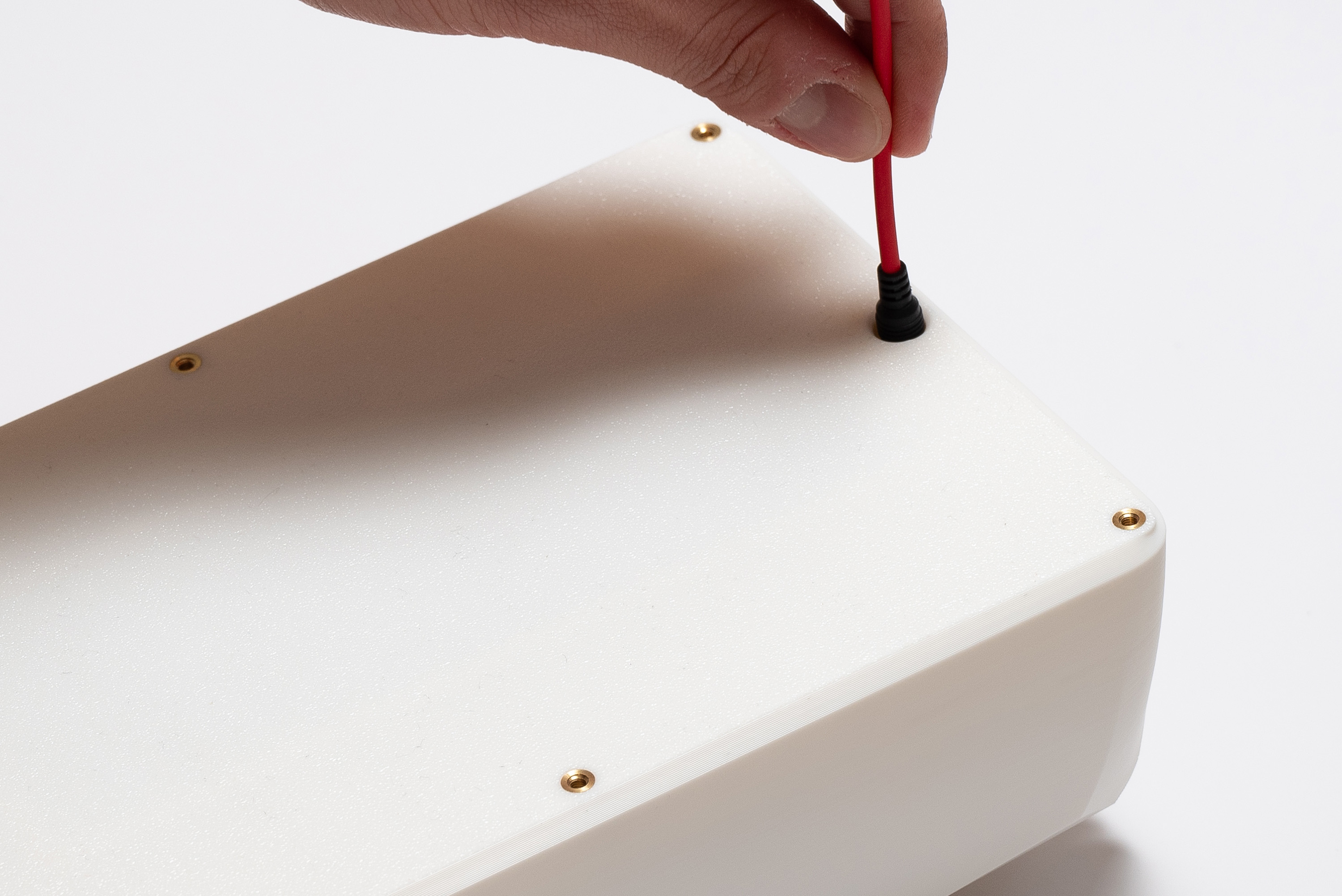
Step 11 – Solar Panel
Align the panel to make sure the cable is going out backwards, then pass it through the hole:
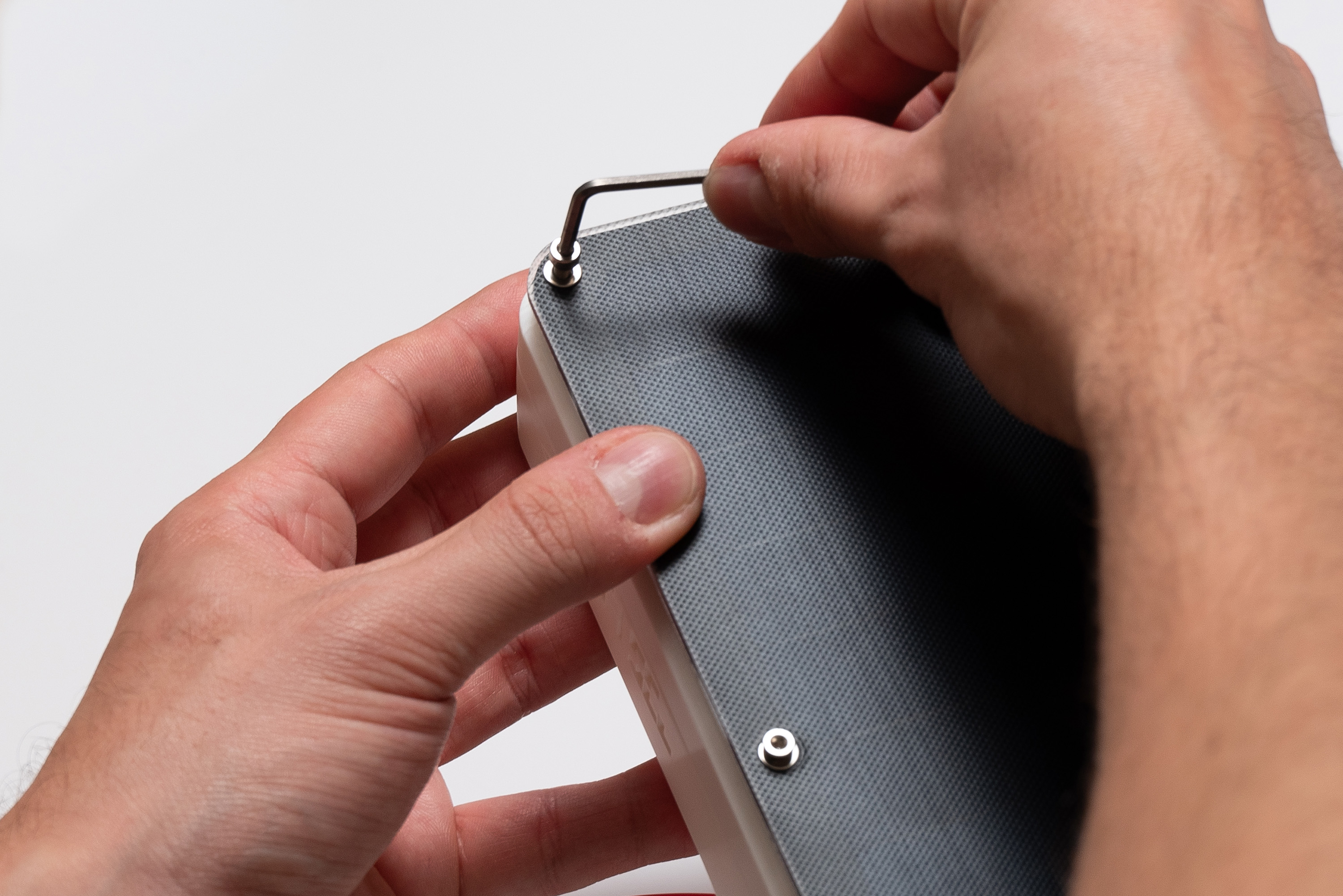
There are six holes to secure the solar panel to the top piece. Pick up 6x M3X16 screws + 6x M3 washers and 6x 5mm spacers.
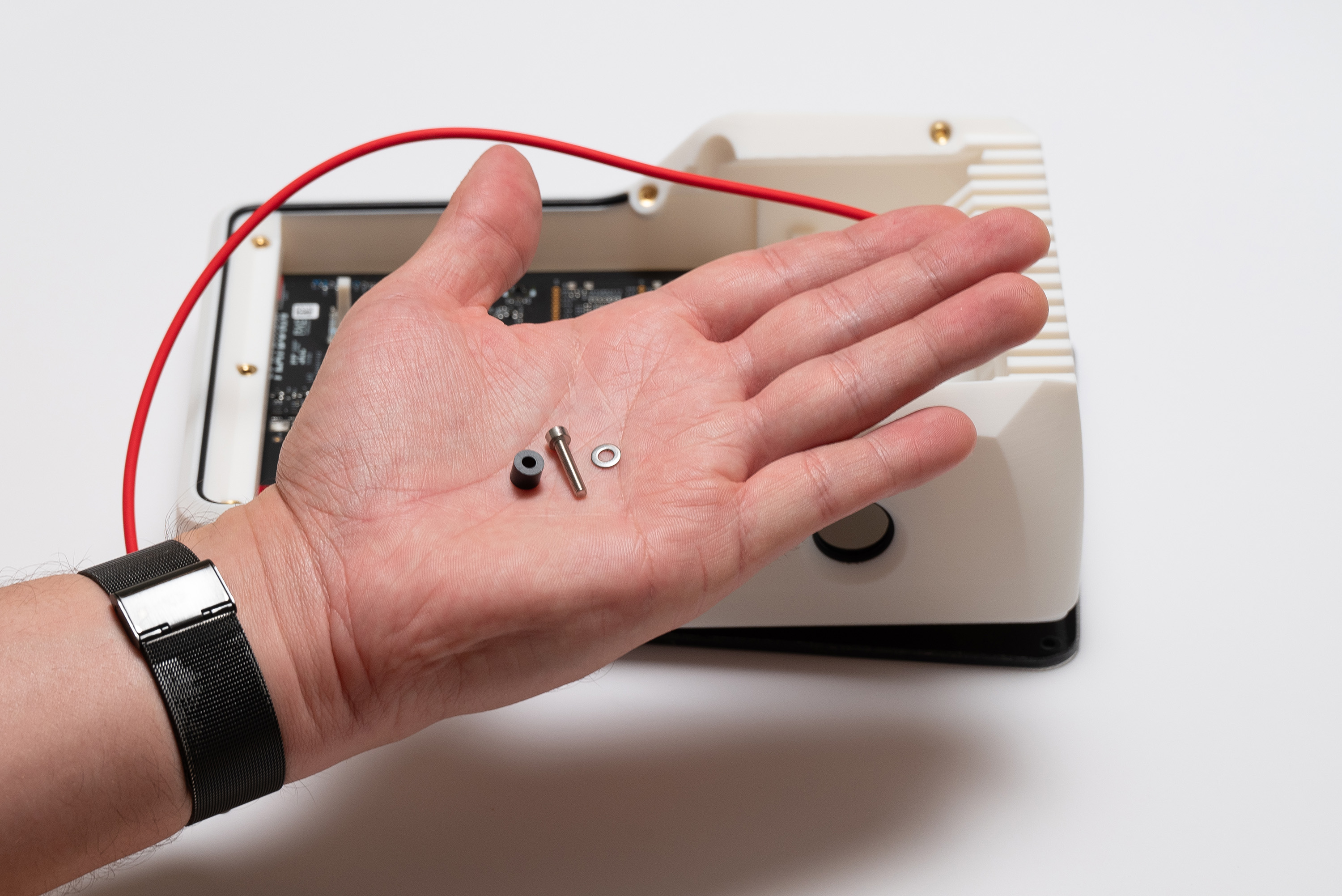
The correct order is screw → washer → Solar Panel → spacer → top piece:
Start with both the intermediary holes, since that will make it easier to align the Solar Panel to the top piece:
Proceed to the corners:
Due to variation of manufacturing tolerances, it might be harder to fasten these corner screws.
Make sure the screw is properly aligned to the insert on the top piece and fasten while making sure it is following the right angle.
✅ Result
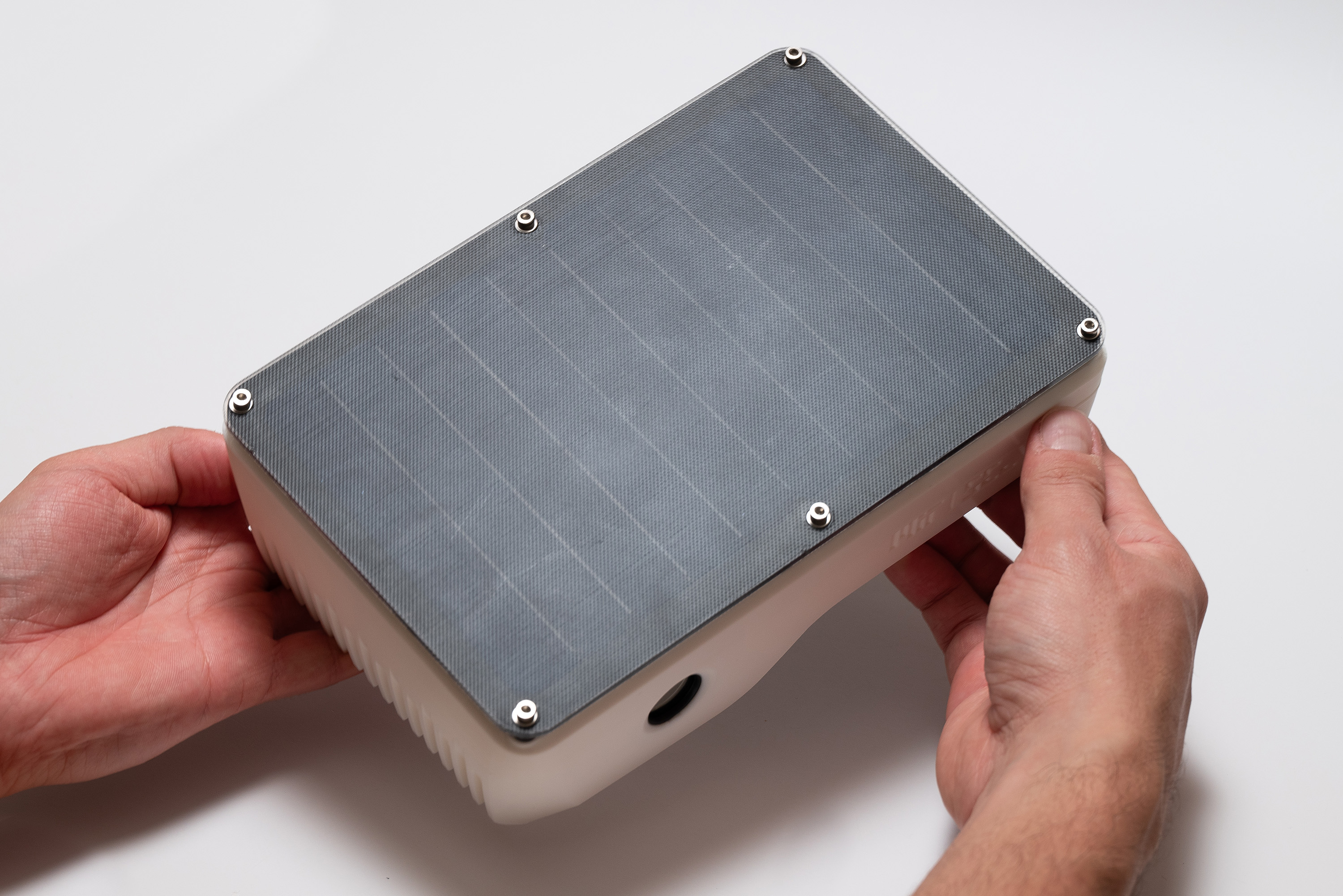
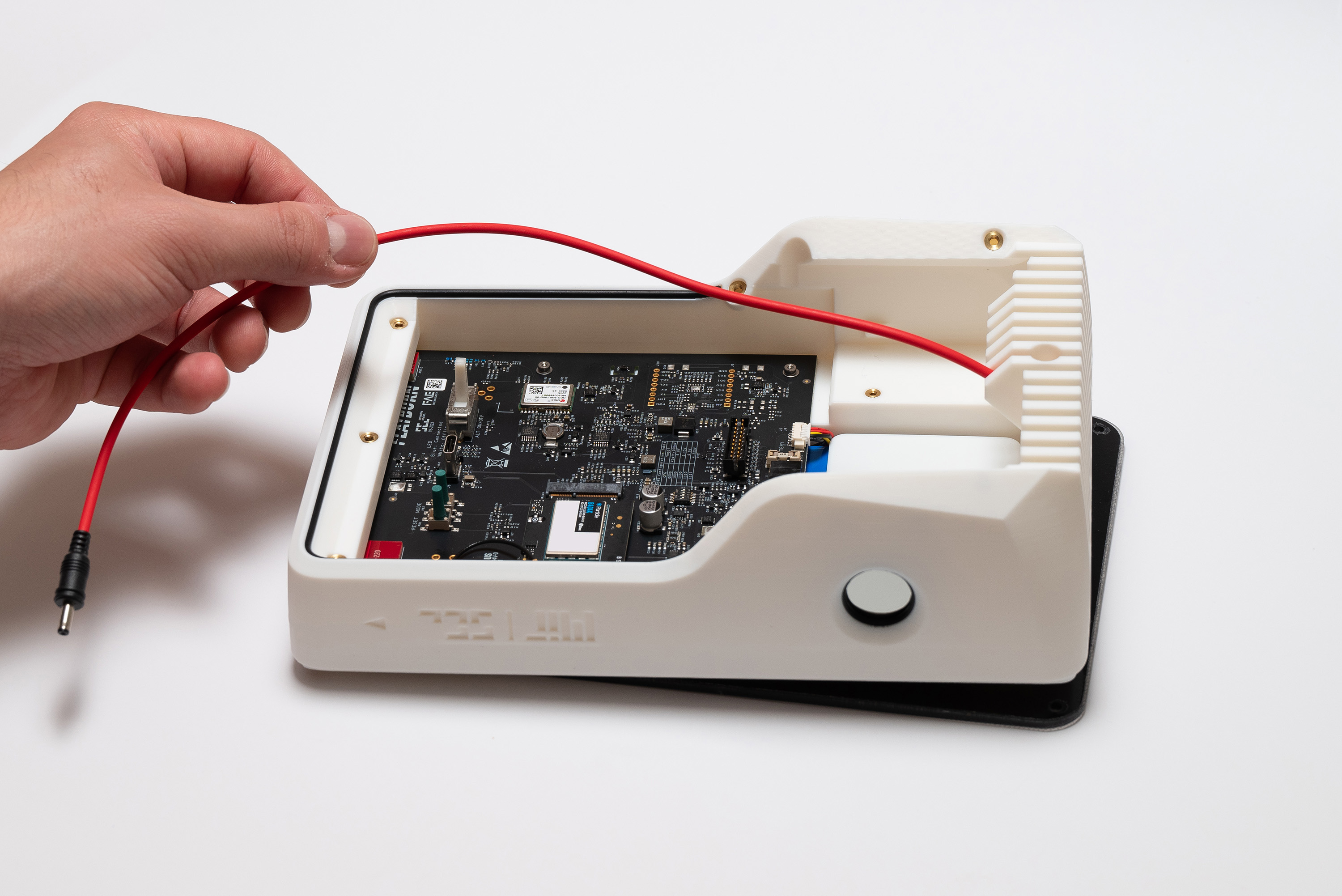
Please make sure there is no surplus of cable above the top piece, all excess should be below:
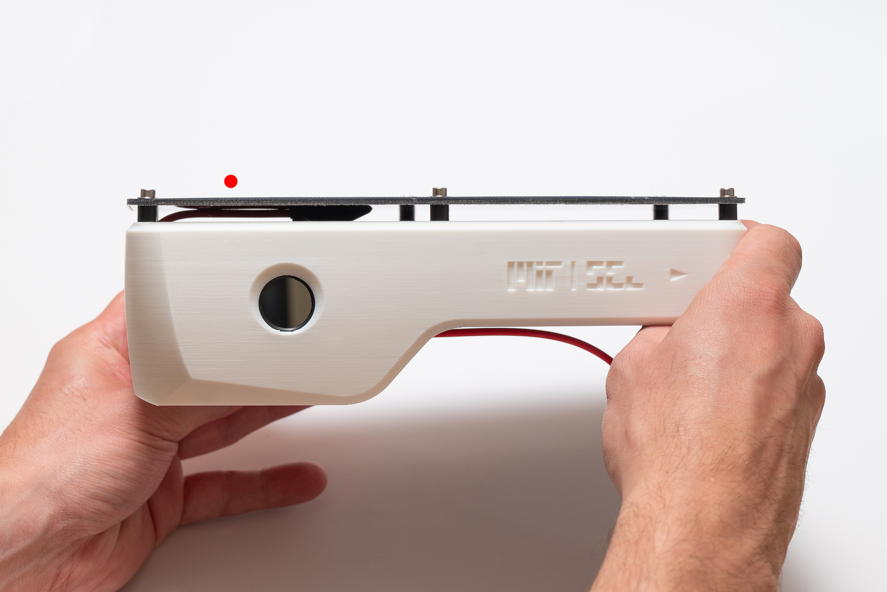
Gently wind the cable while making sure it enters through the indicated spot on the back of the top piece and respects the boundaries of its compartment above the battery_holder:
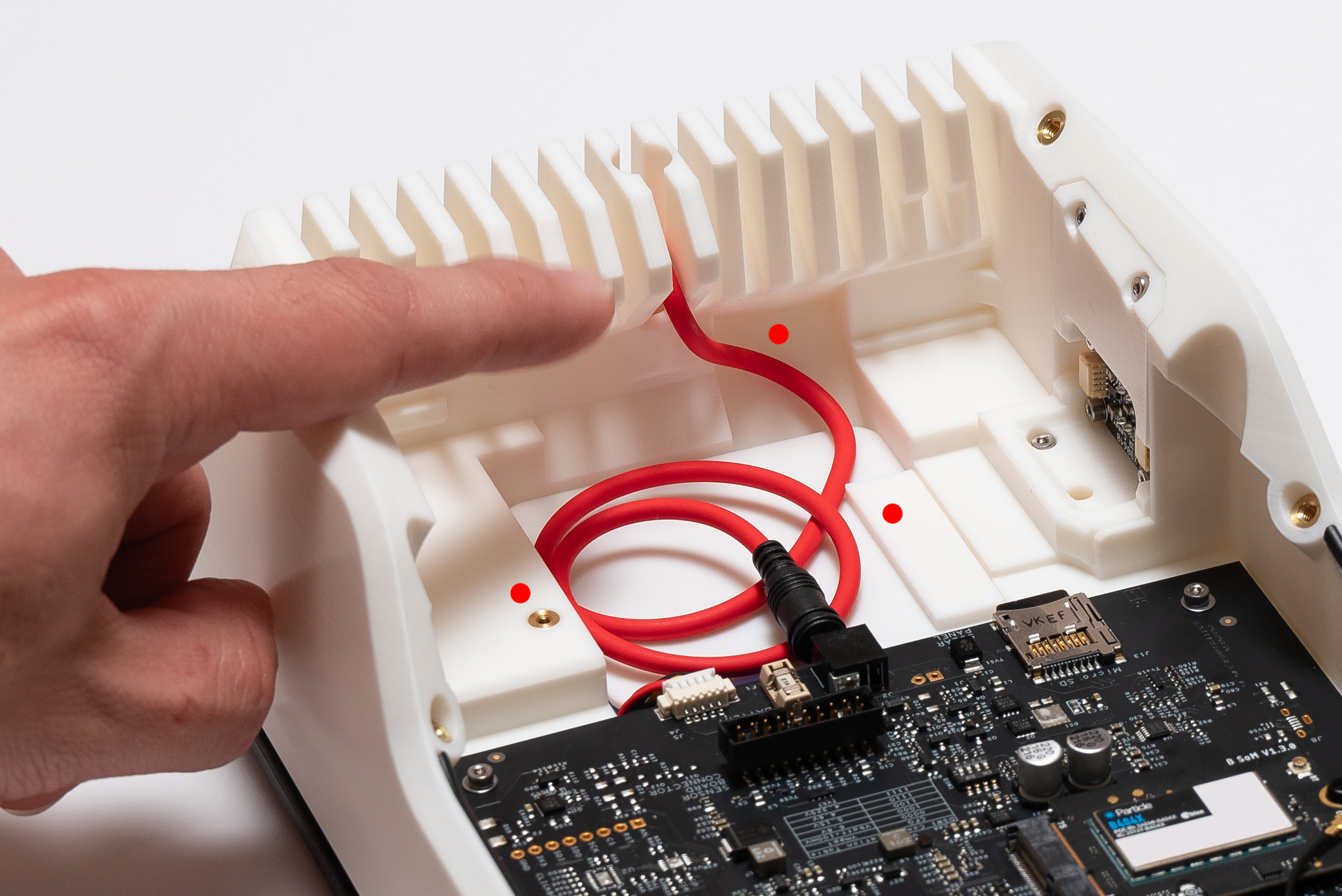
Attach the connector to the Main Board socket:

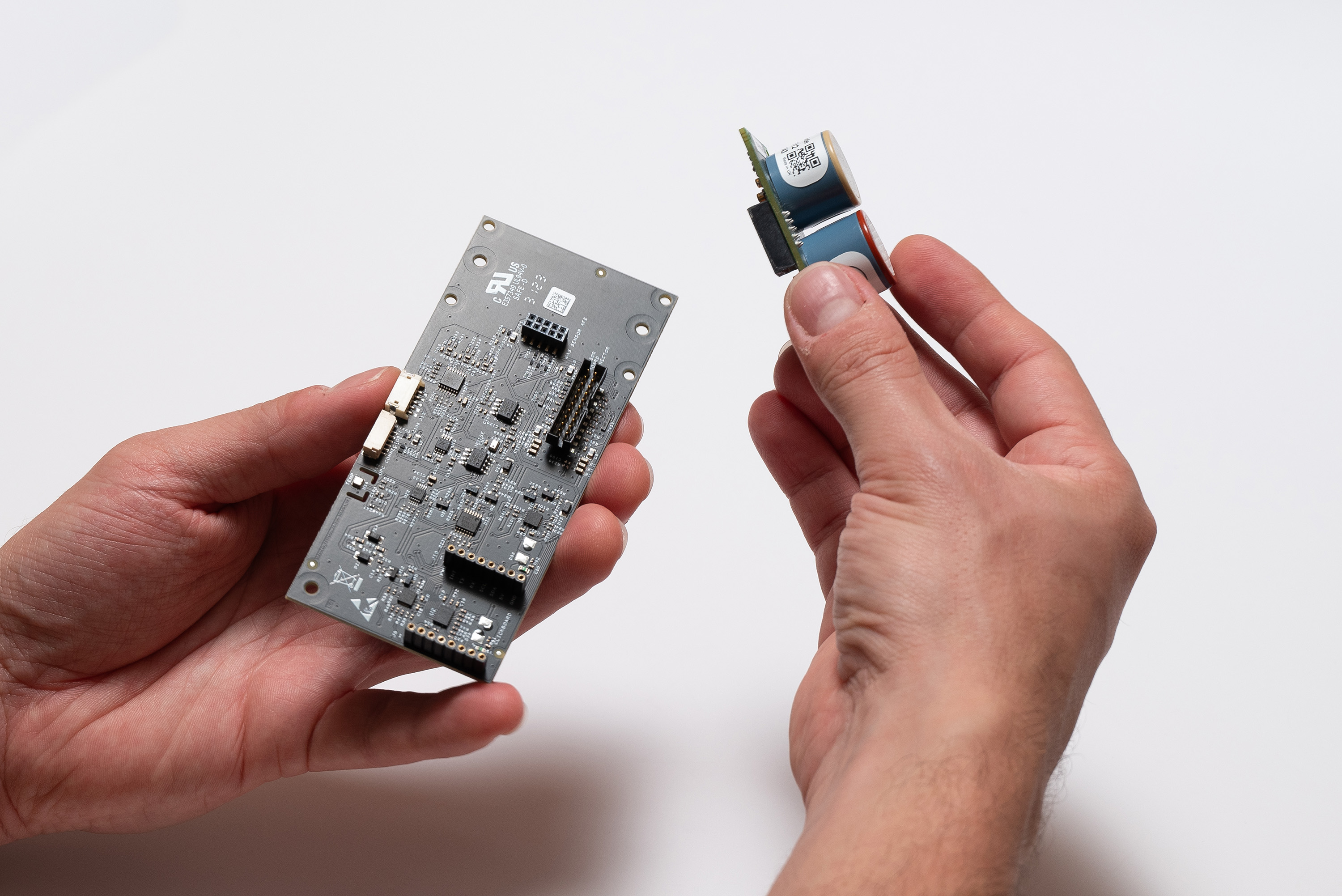
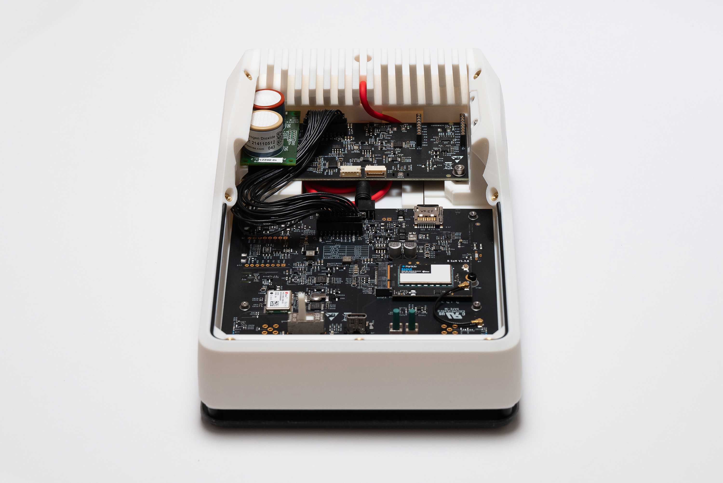
Step 12 – Sensing Board
Depending on your needs, choose the appropriate gas sensor: CO+NO2 or O3+NO2 (depicted).
More information here.
First, start by assembling the desired Alphasense AFE board module into the Sensor Board:
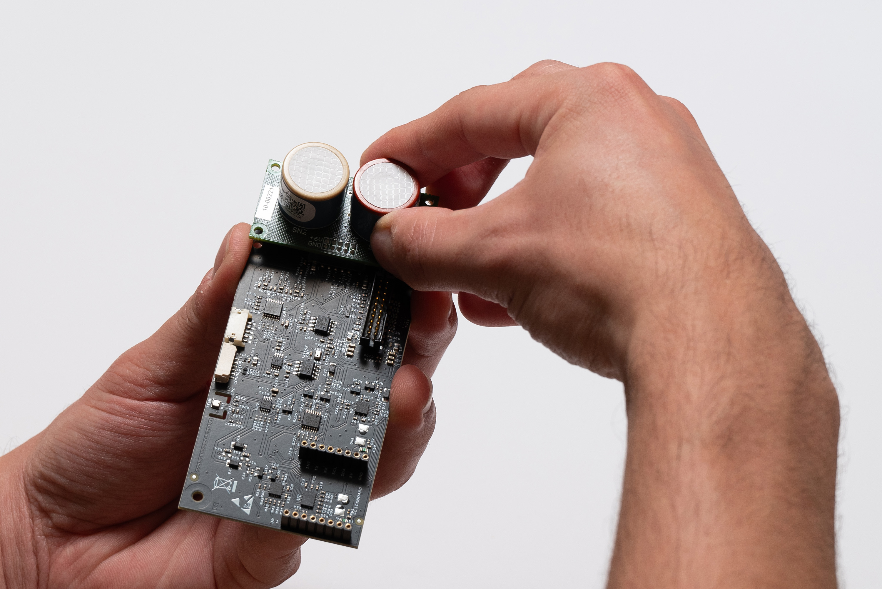
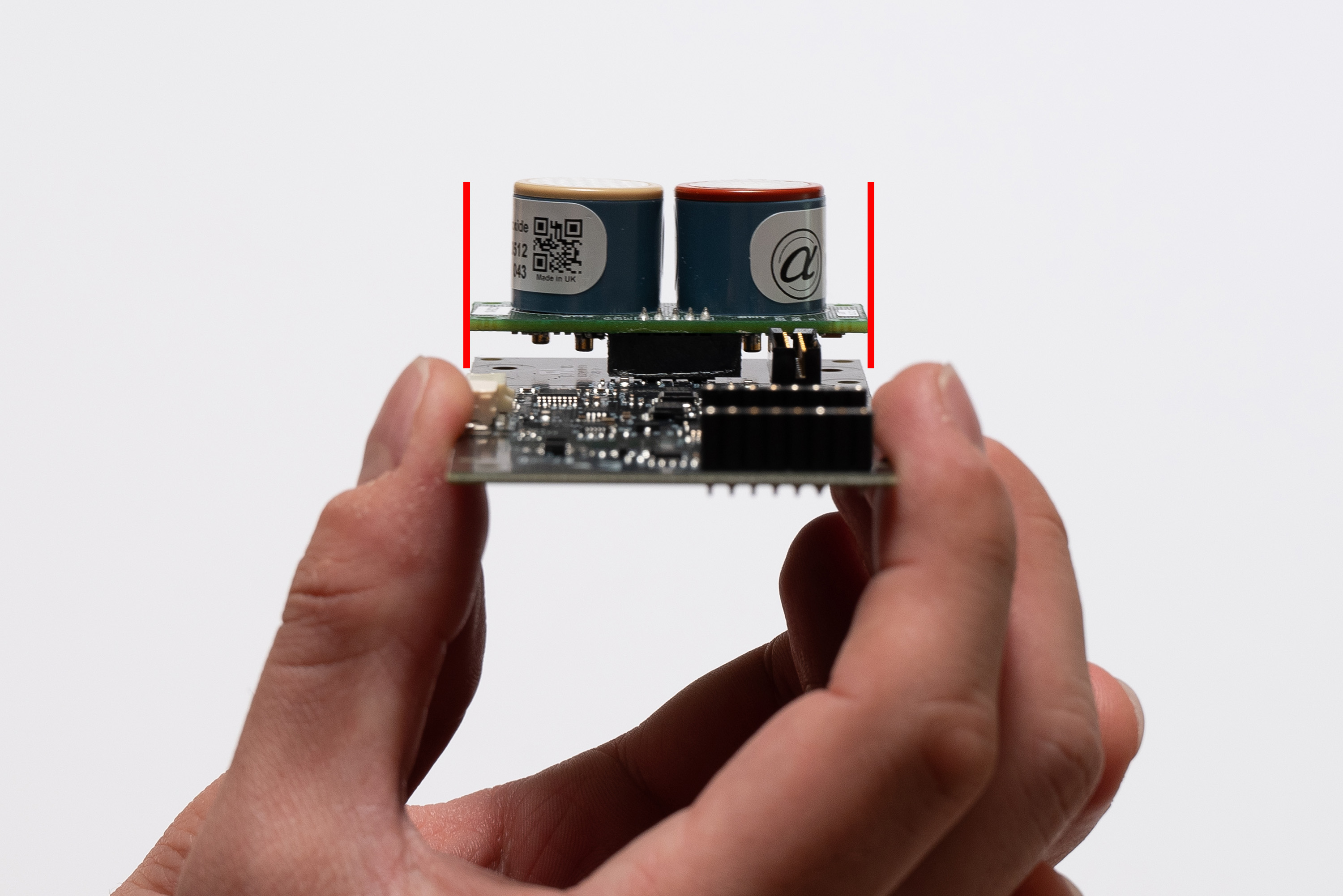
Make sure the module is properly aligned, because it is easy to attach it wrong.
The module sides must be parallel, and aligned to the Sensing Board edges.
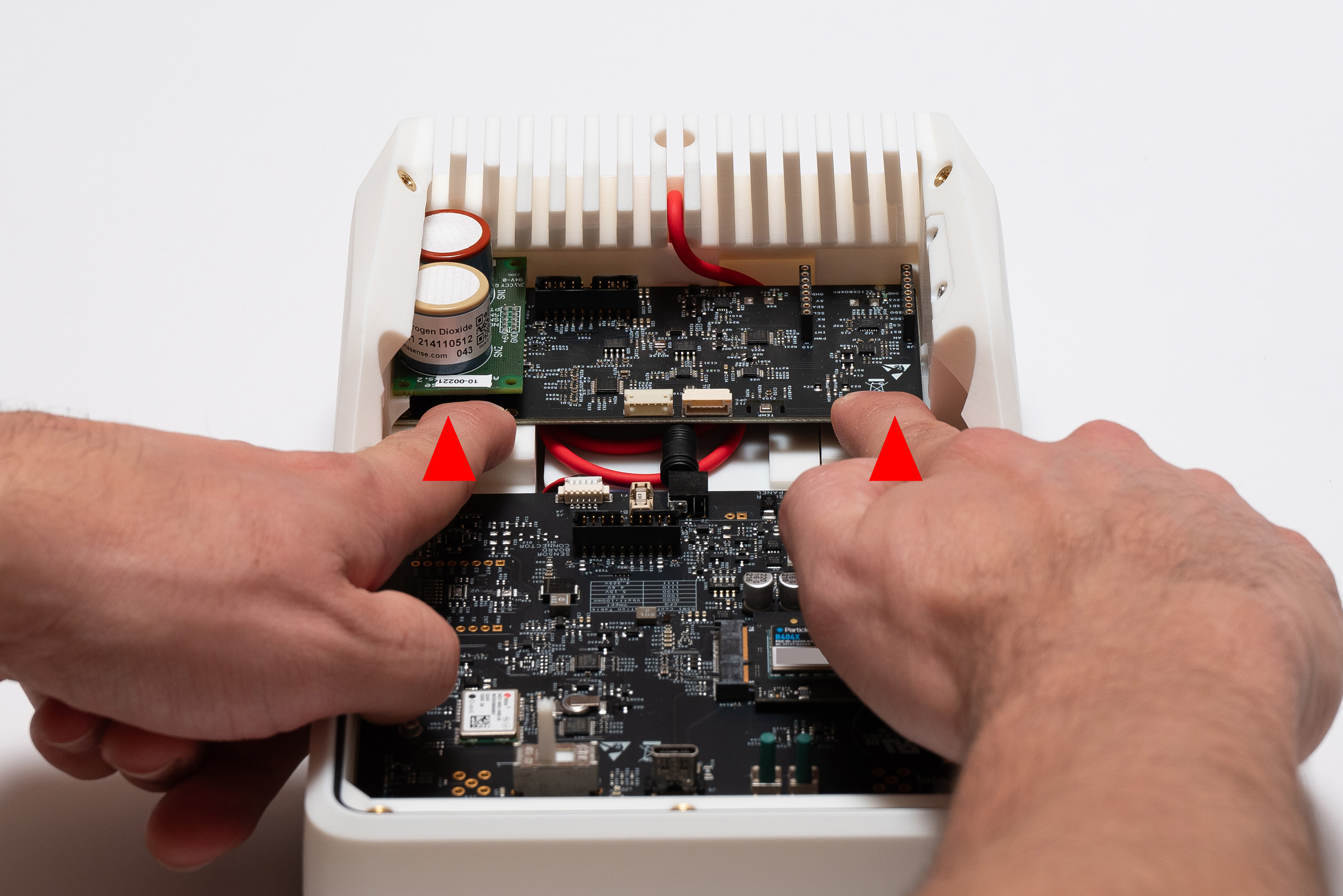
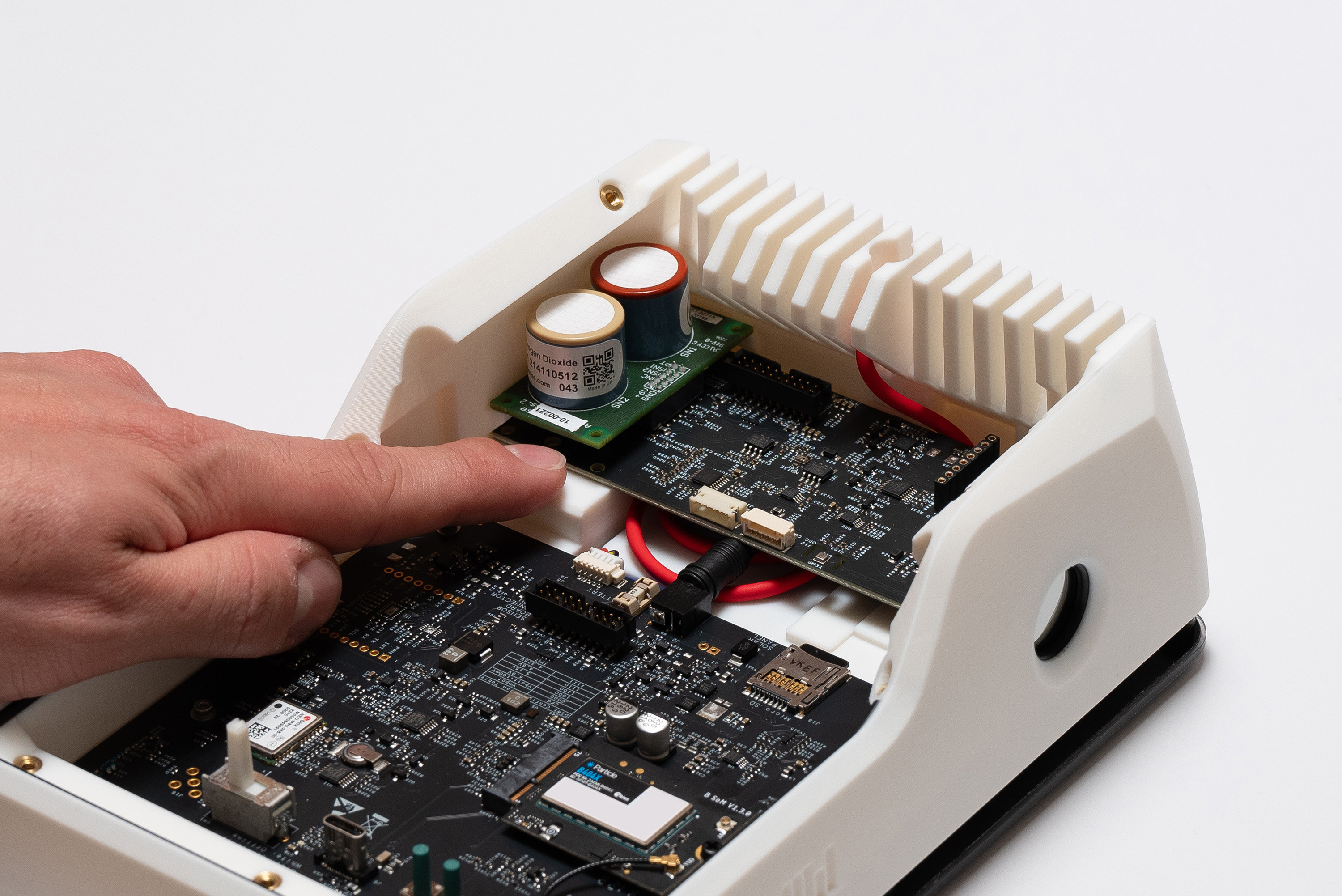
To place the Sensing Board into the top piece, fit it into the back part while keeping it angled:
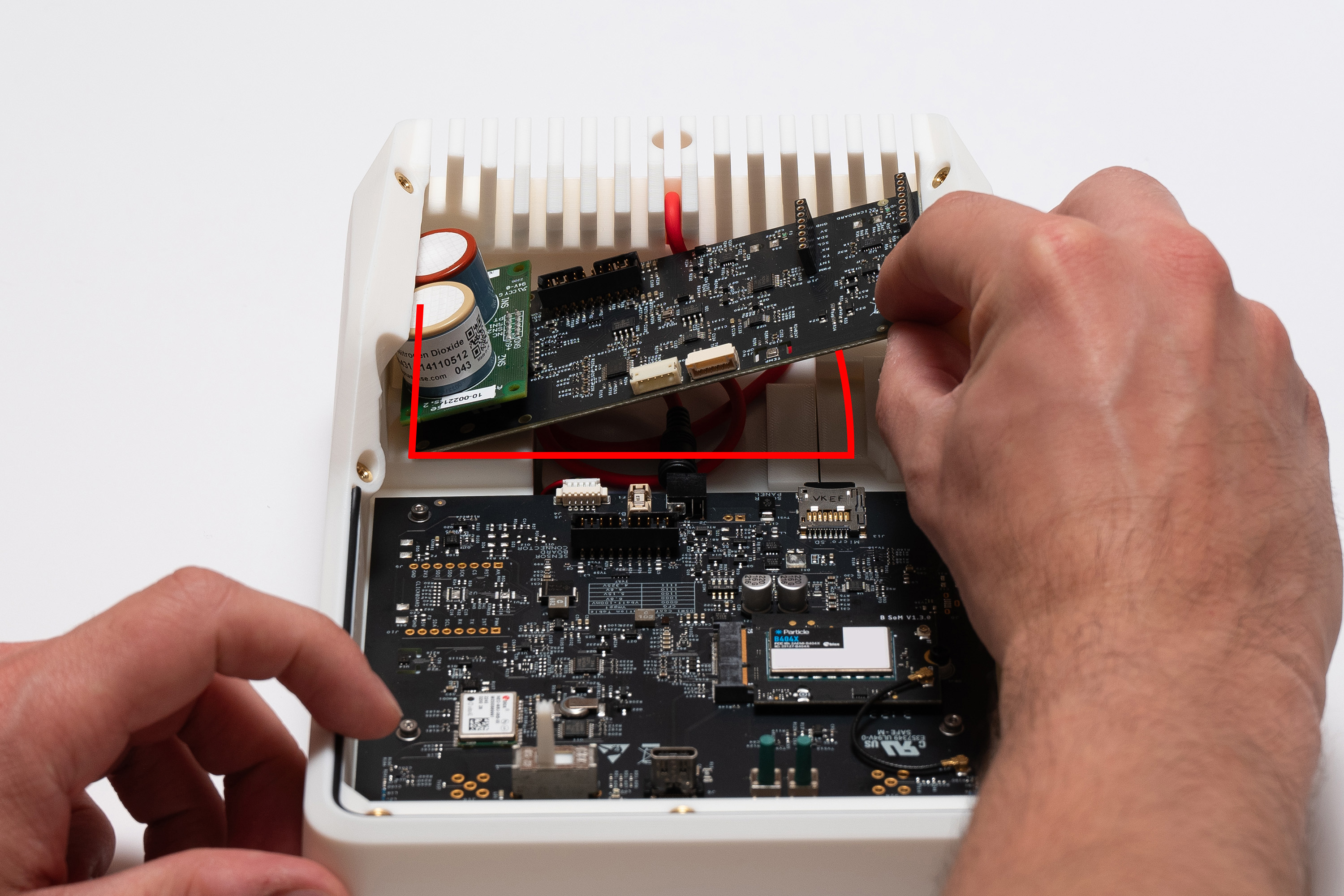
Swing it down, while paying attention to the fitting on the left side:
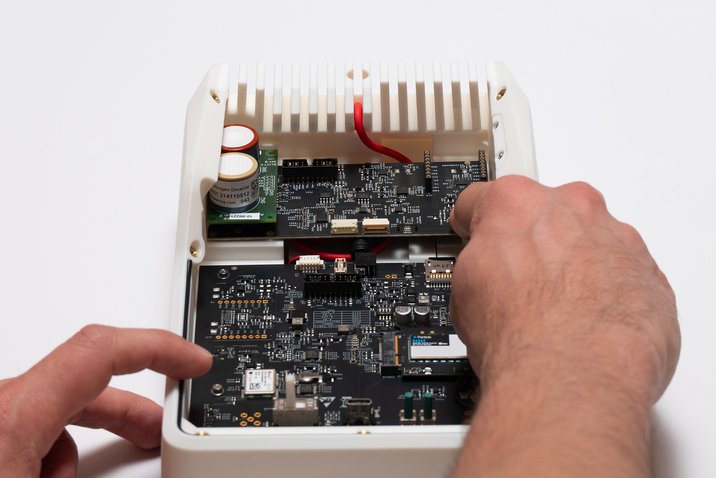
Finally, slide the Sensing Board away, making sure the Solar Panel cable is on the proper place:
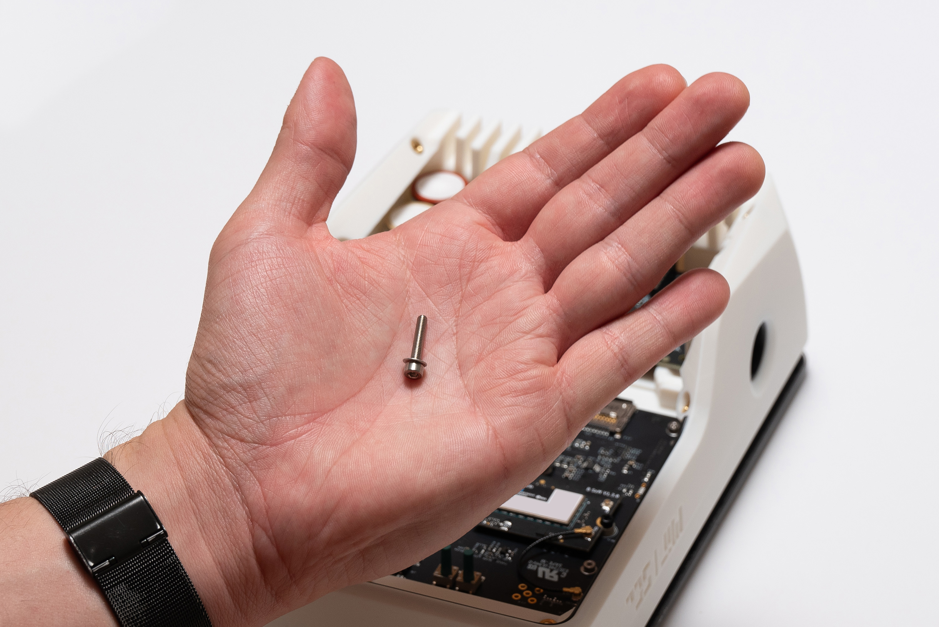
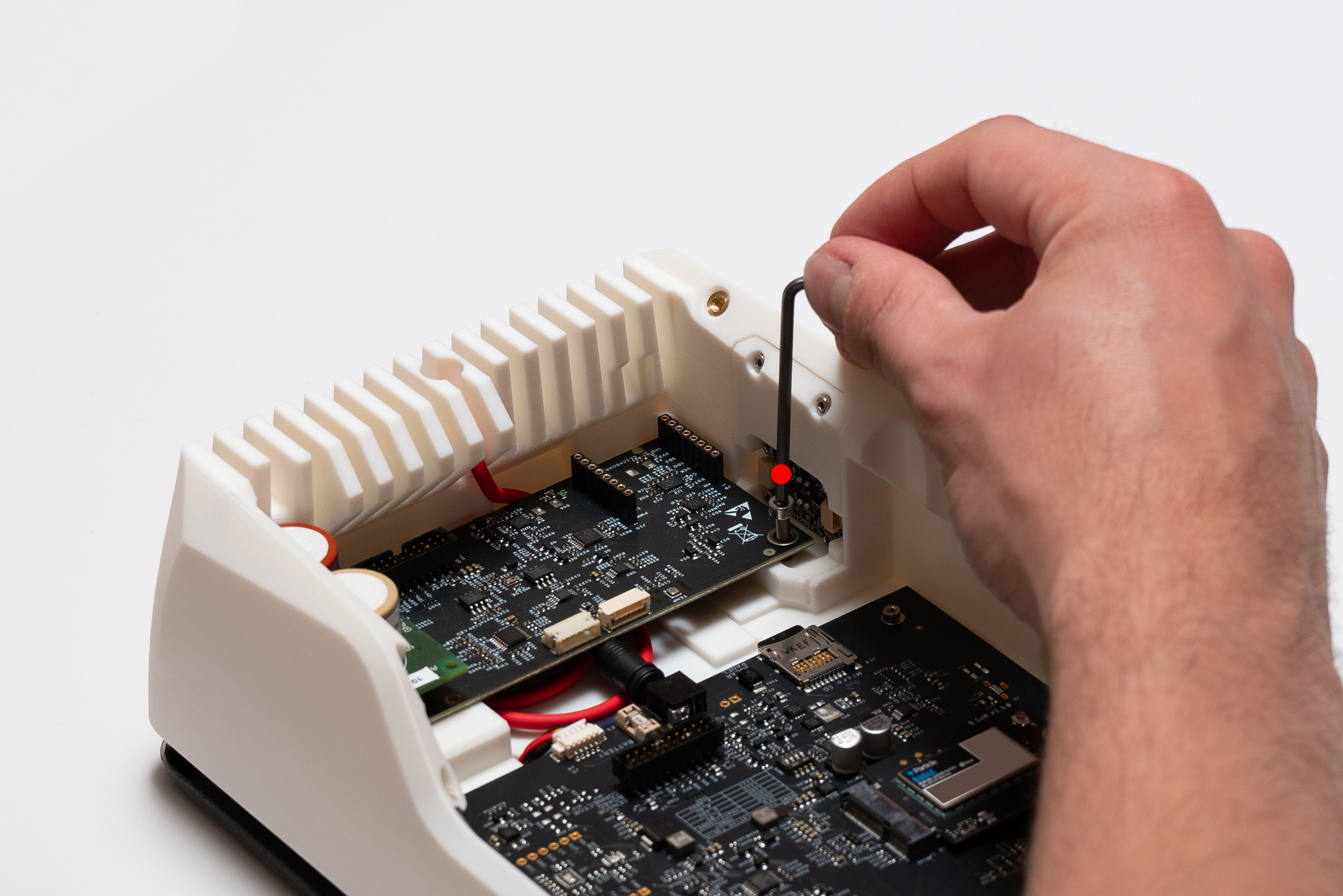
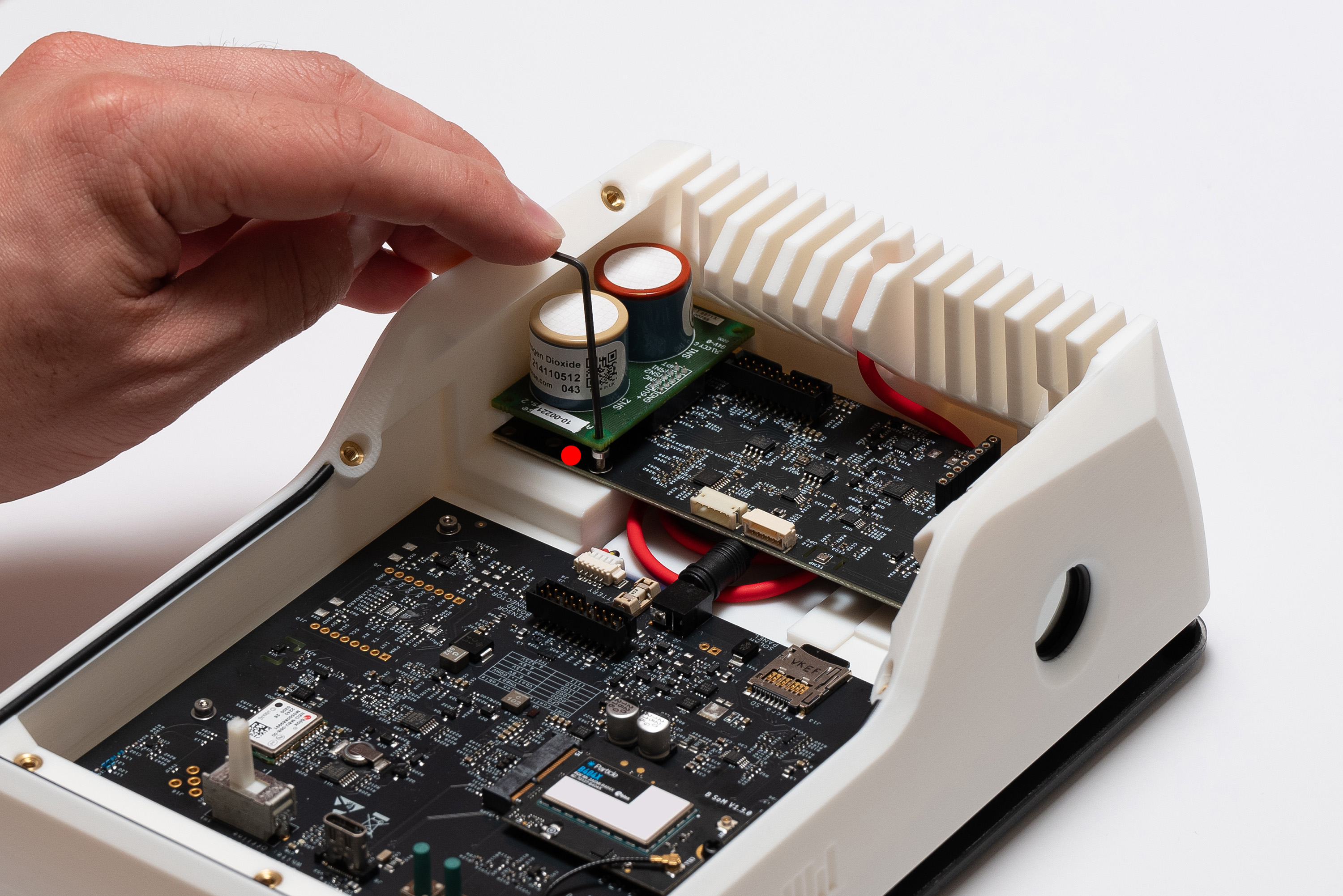
To secure the Sensing Board, pick 1x M3X16 screw with 1x M3 washer and fasten it into the right hole.
Do not fasten the M3 screw excessively or you might damage the Sensing Board.
It should be enough just for the Sensing Board to be held at place
Finally, pick 1x M2X6 screw with 1x M2 washer to used on the left hole.
This is trickier since the screw needs to be put underneath the Alphasense AFE board.
You can raise it a little bit if needed, making sure it doesn't get disconnected.
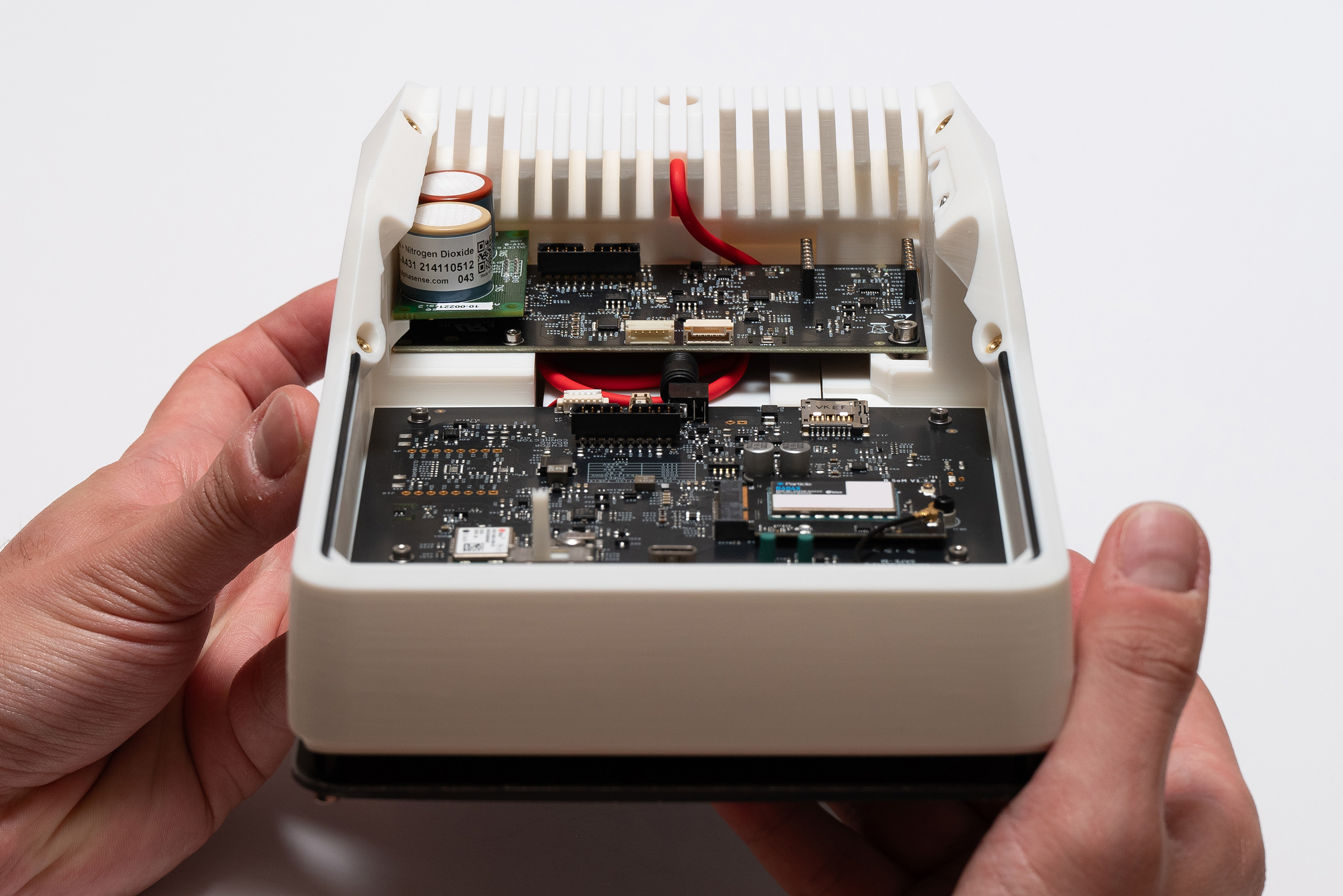
✅ Result
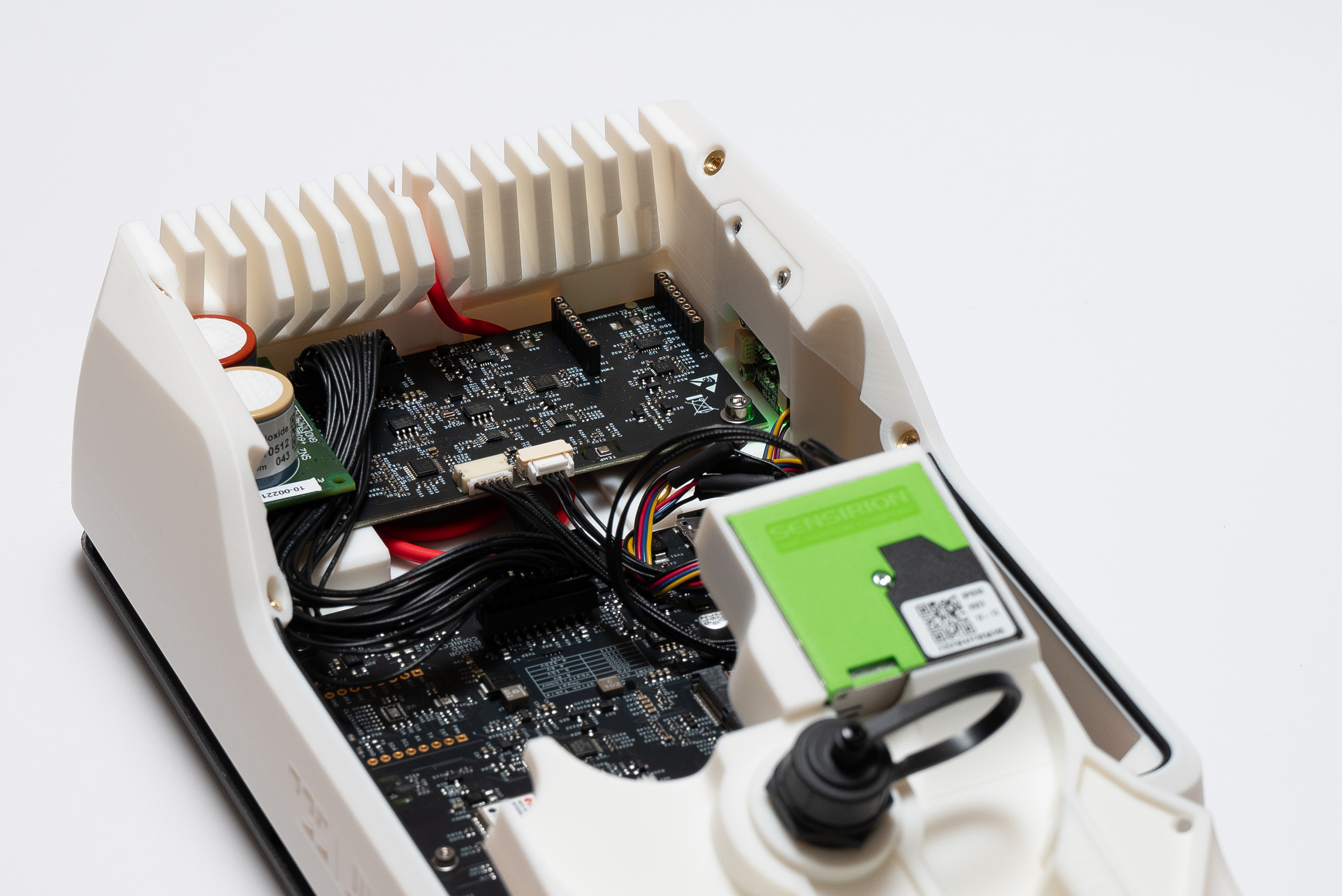
Step 13 – Main Cable
The main cable connects the Main Board with the Sensing Board.
The cable has no specific start or end, but its connectors has only one way to be inserted.
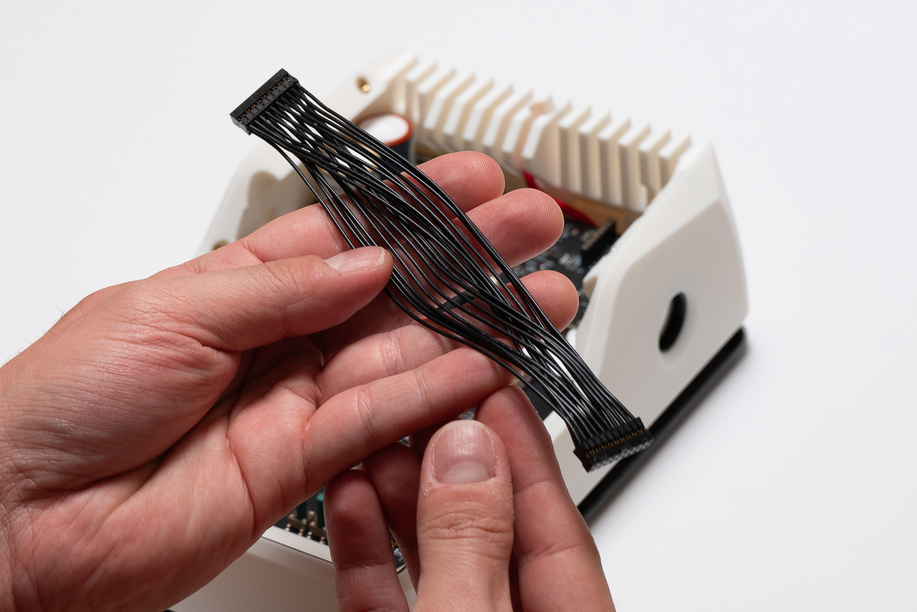
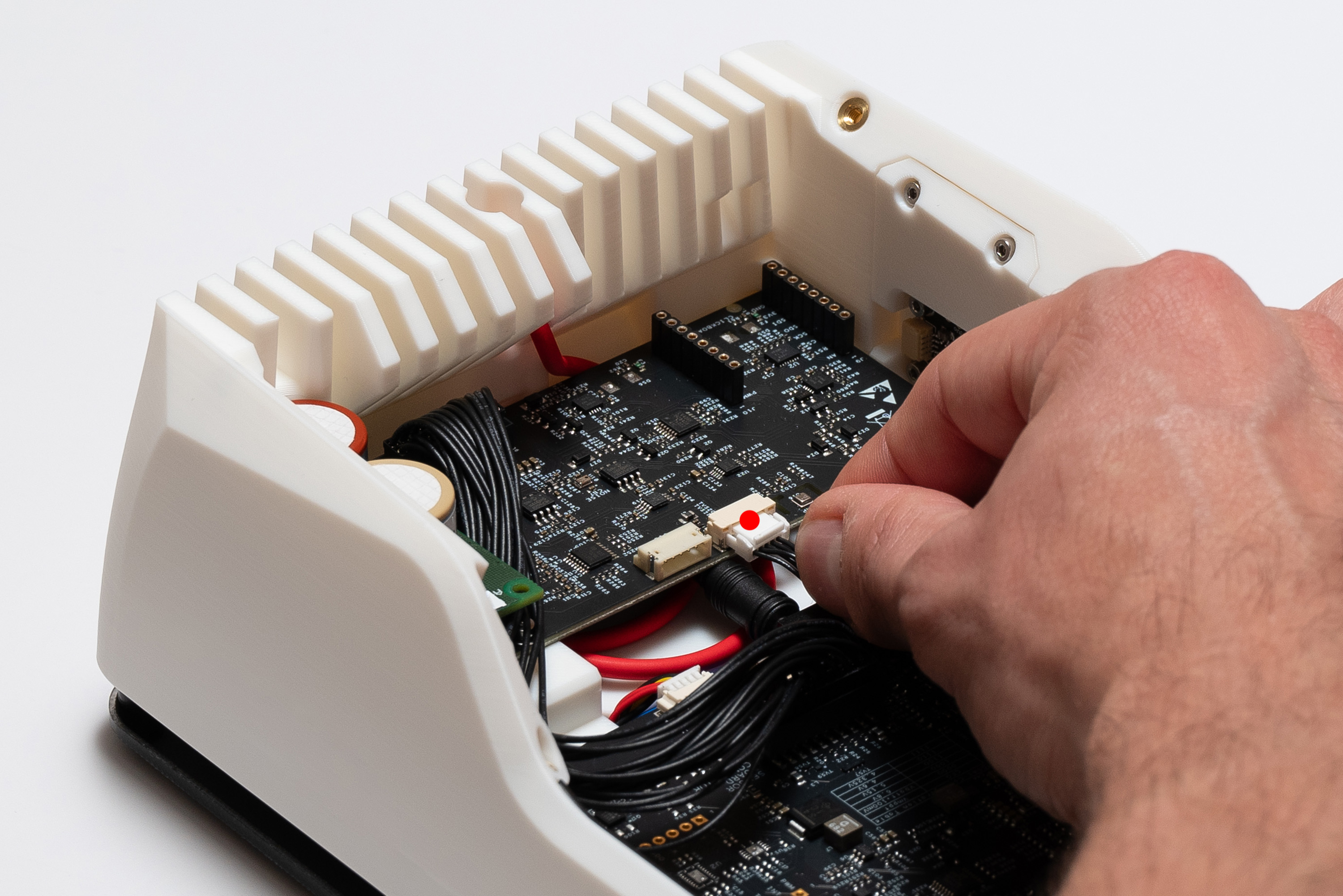
First, connect the cable to the Sensing Board:
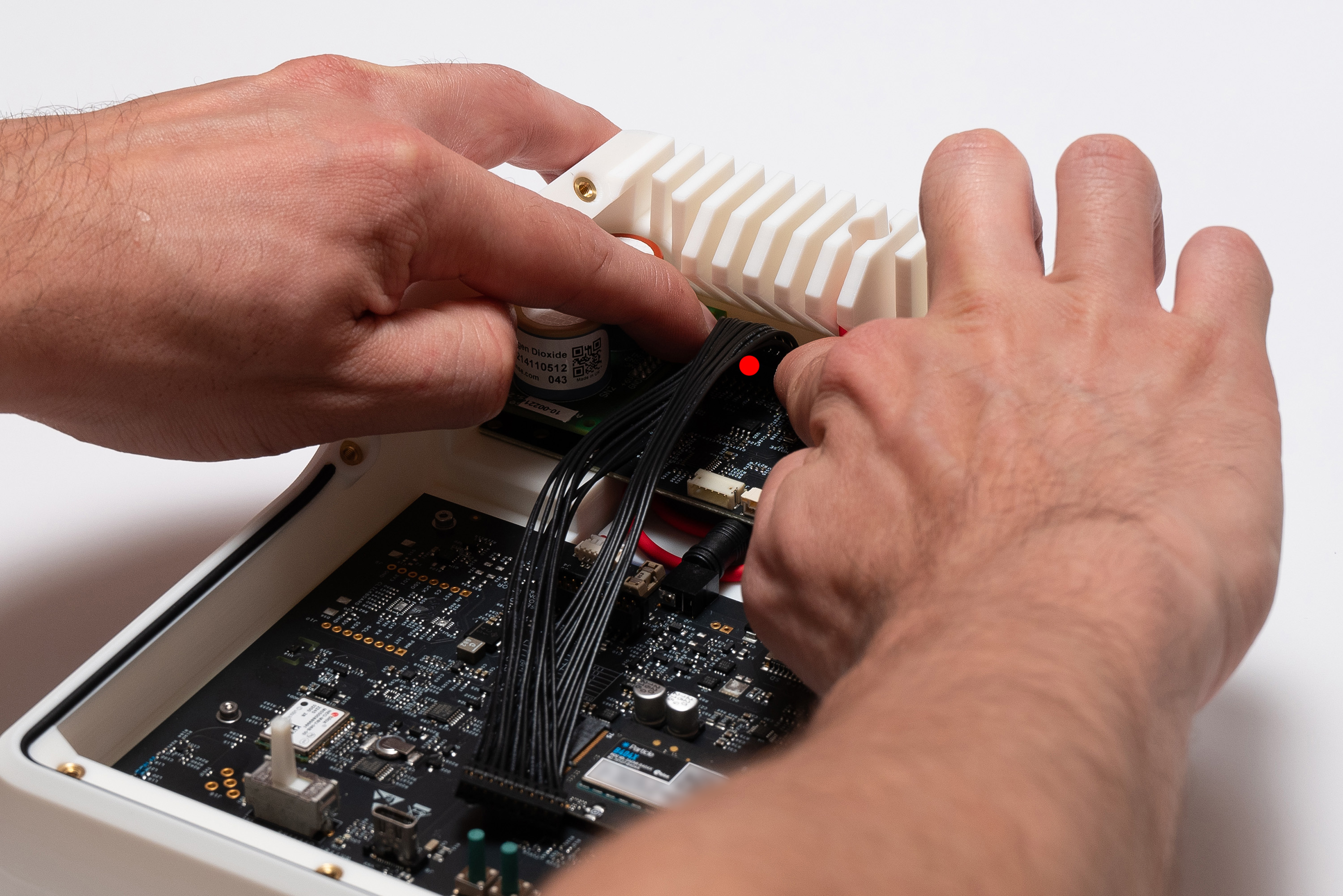
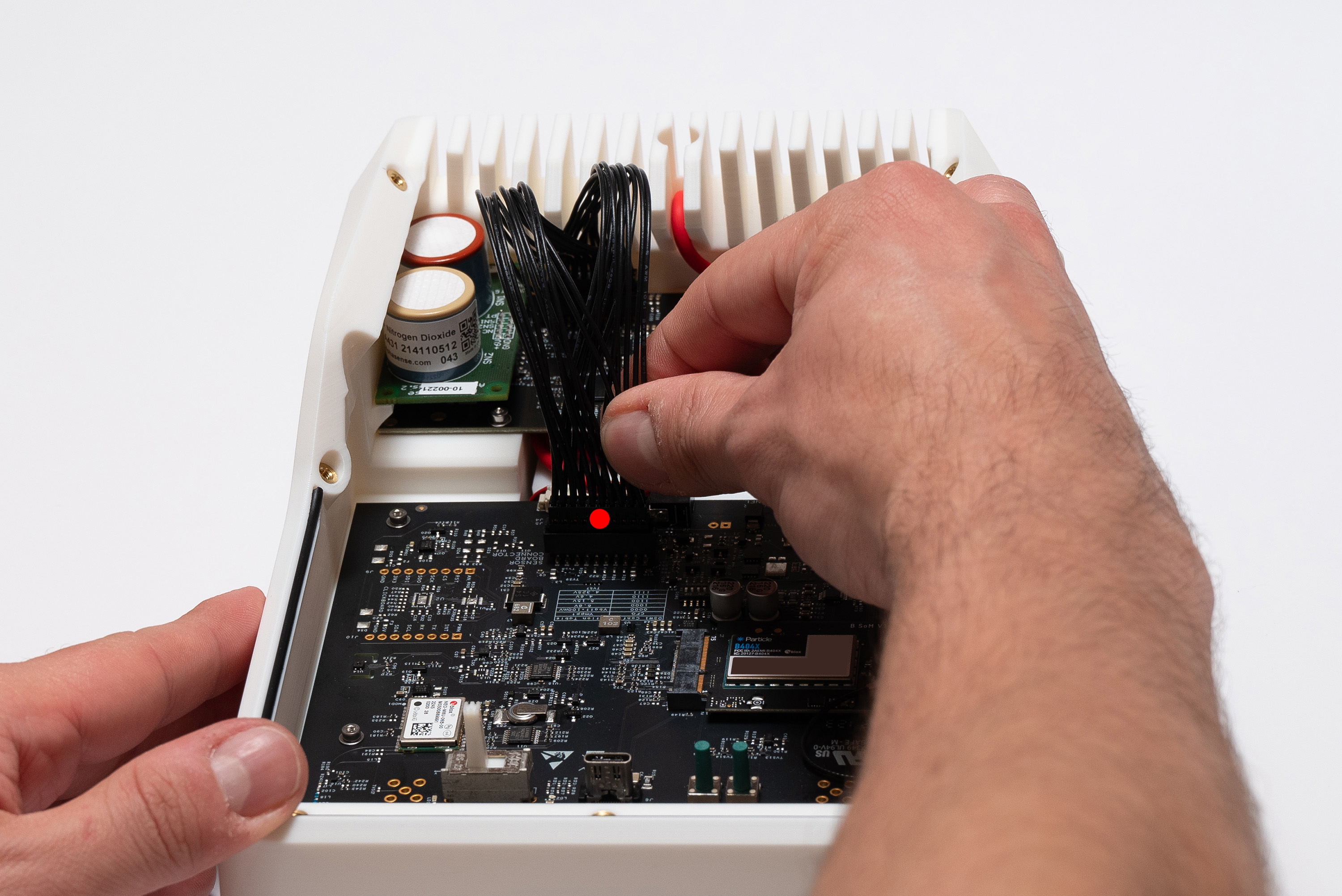
Then, connect the cable to the Main Board:
To organize the cables, place them underneath the Alphasense AFE board.
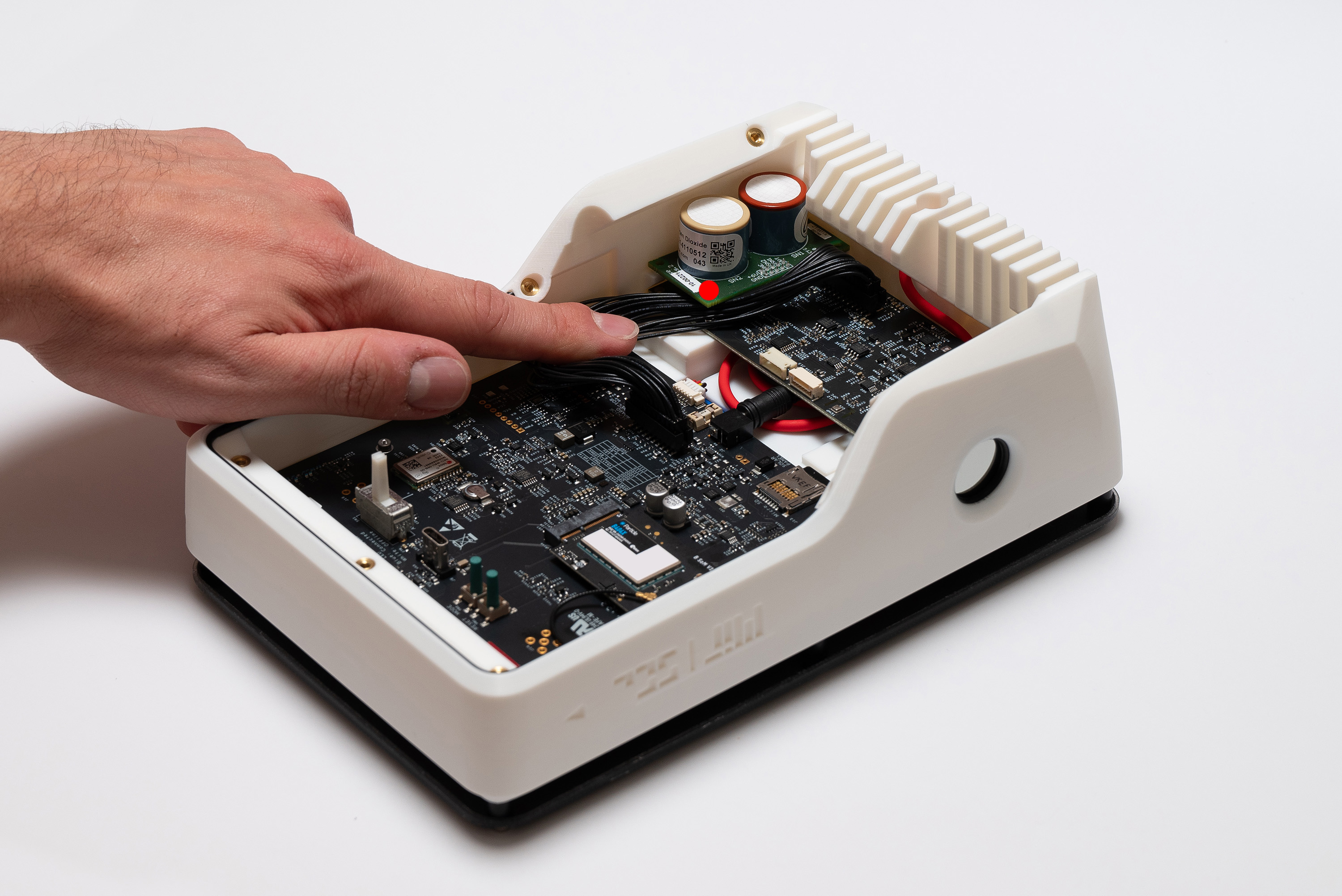
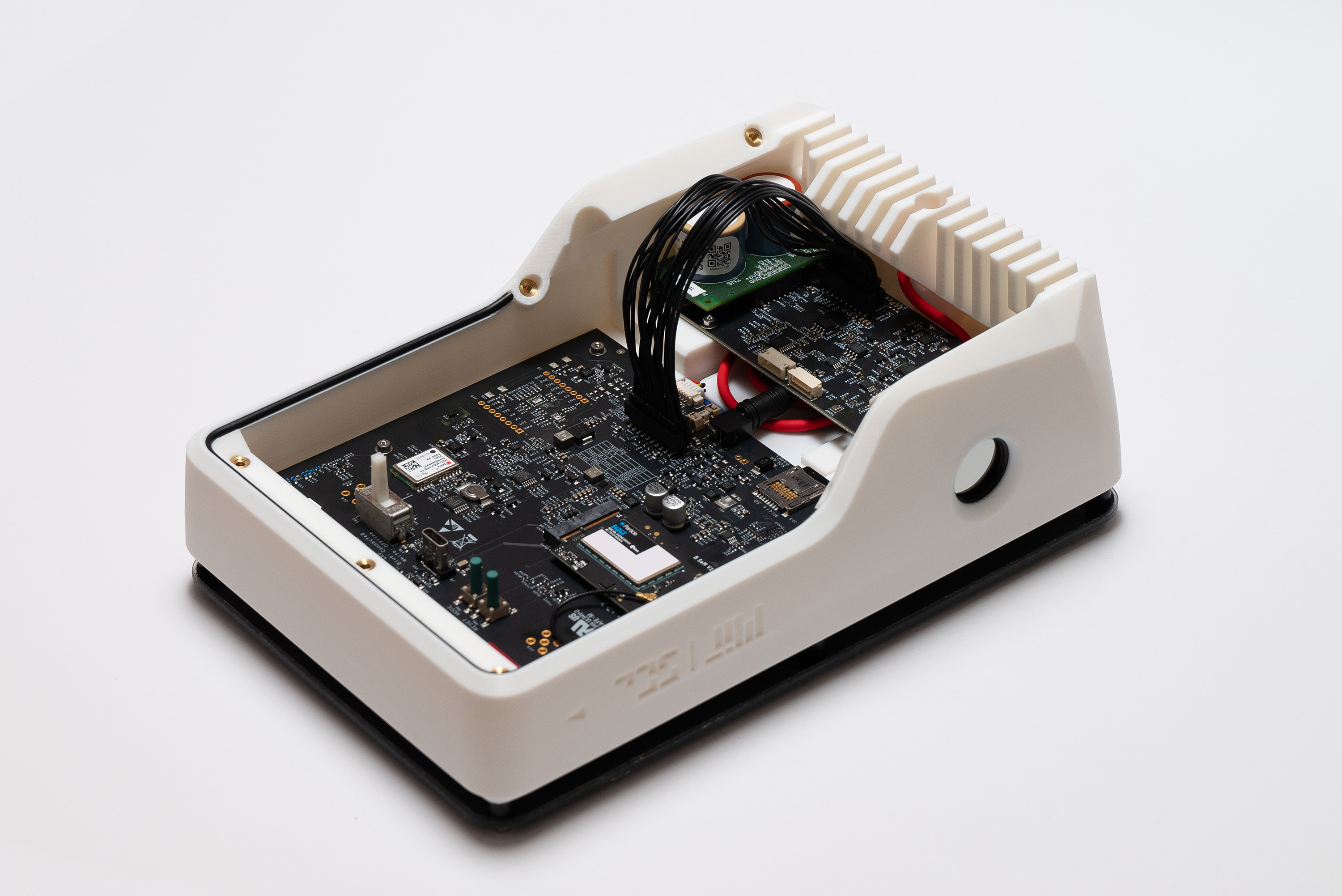
✅ Result
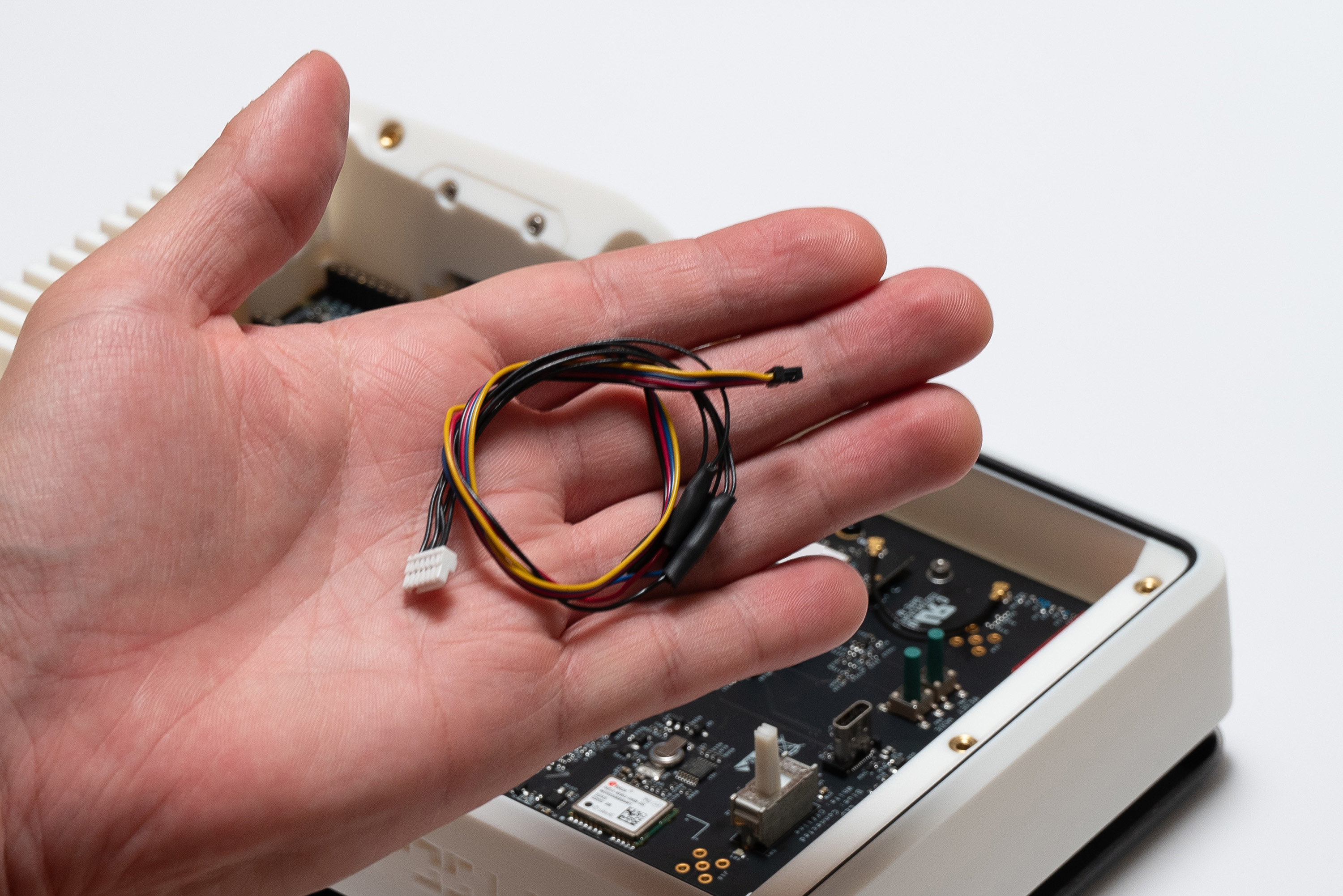
Step 14 - Camera Cable
Now you can connect the camera cable, beginning with the camera:
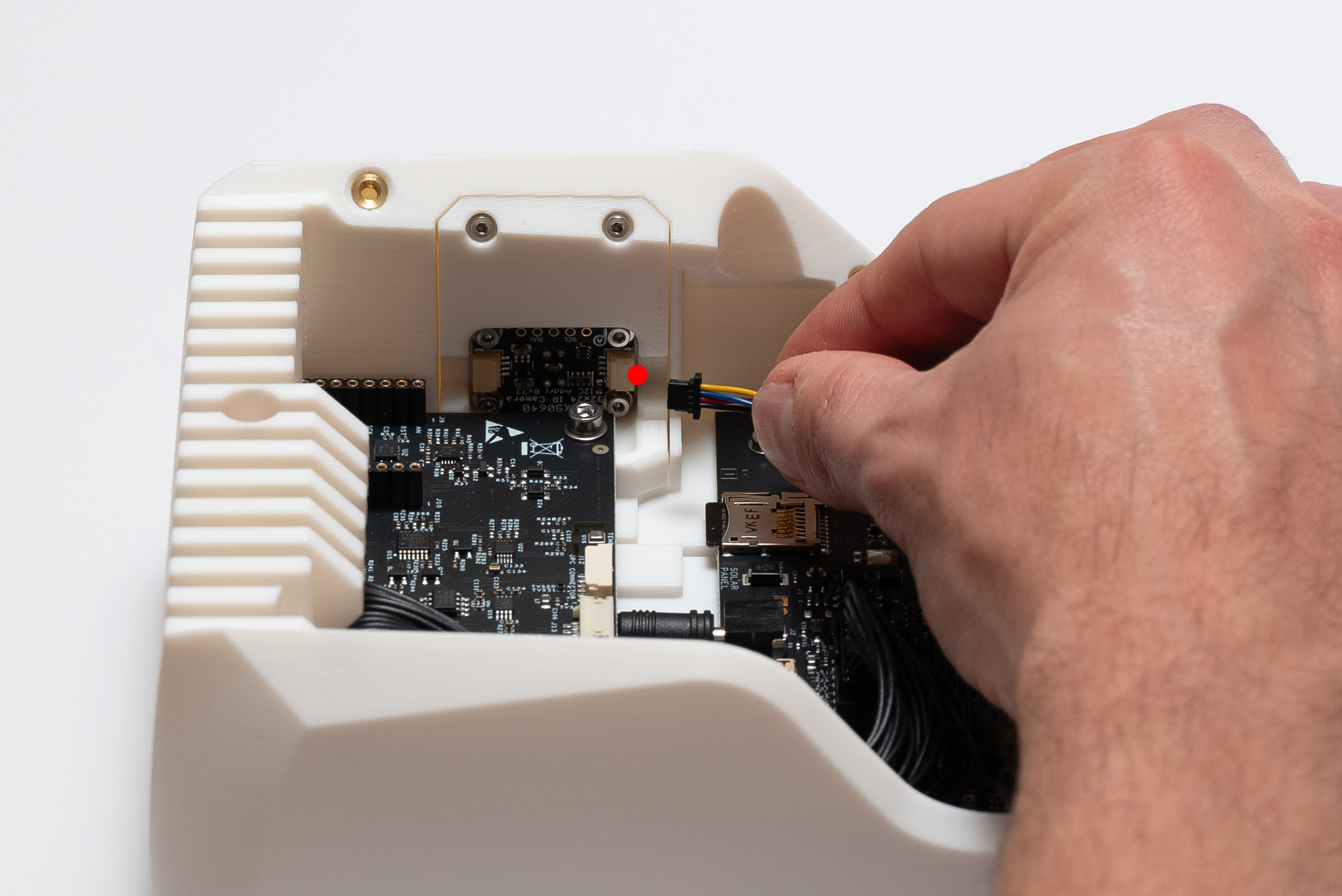
You might carefully use a tweezer or screwdriver to gently push the connector, but take care to not damage anything.
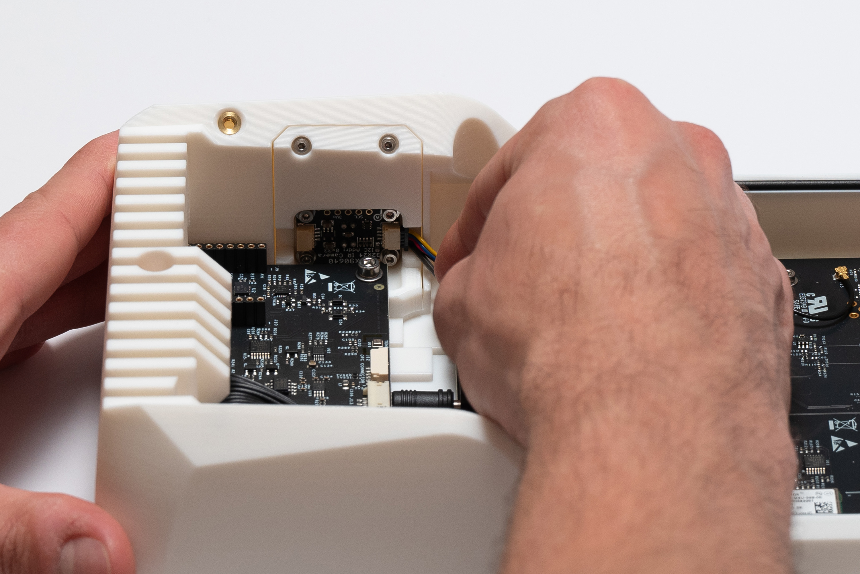
Finally, connect the cable to the Sensing Board:
Step 15 – Switch
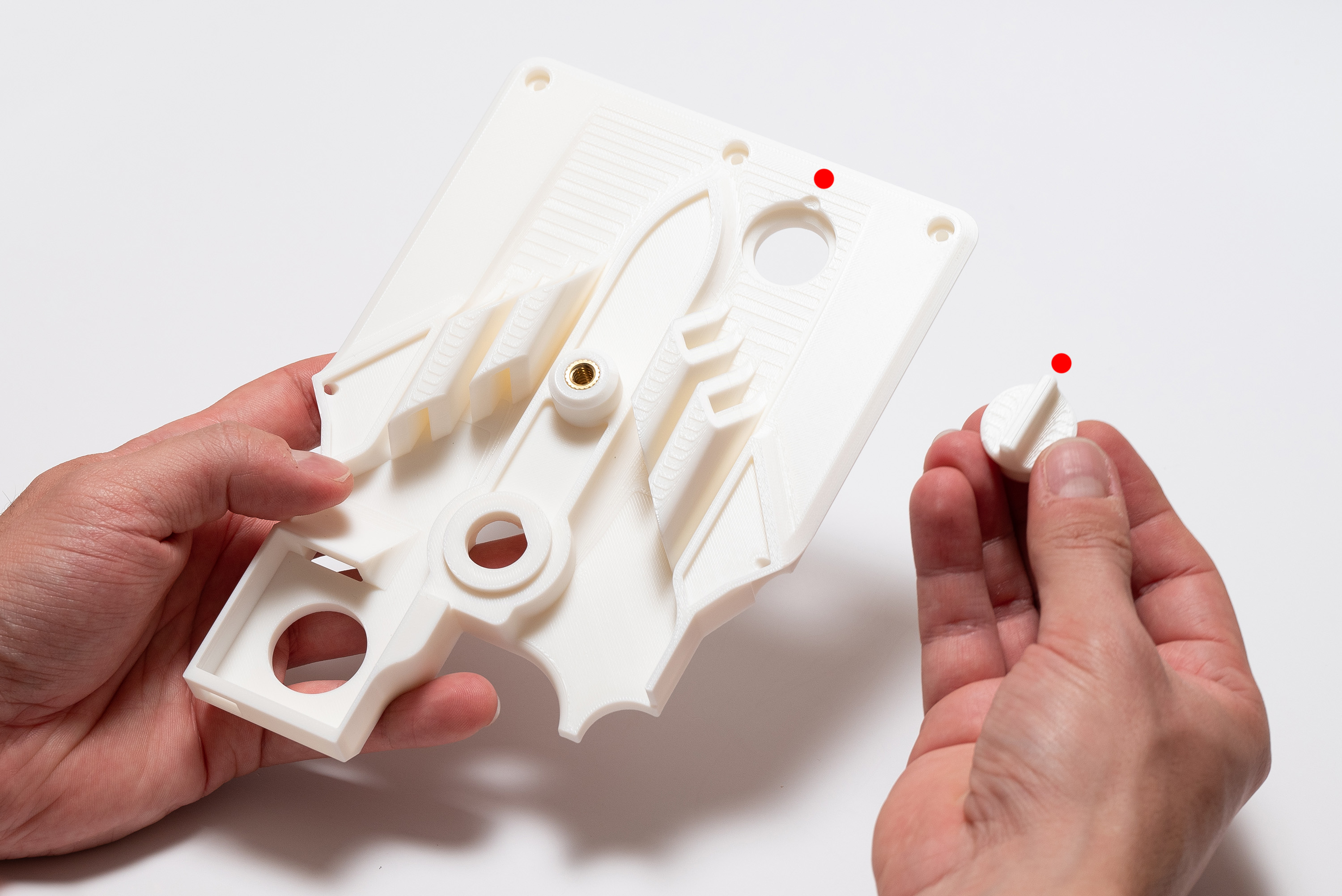
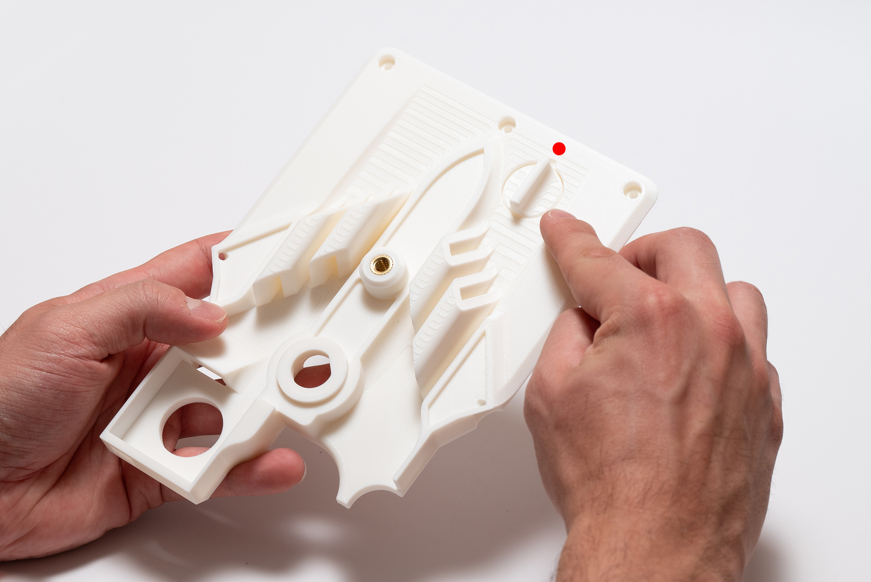
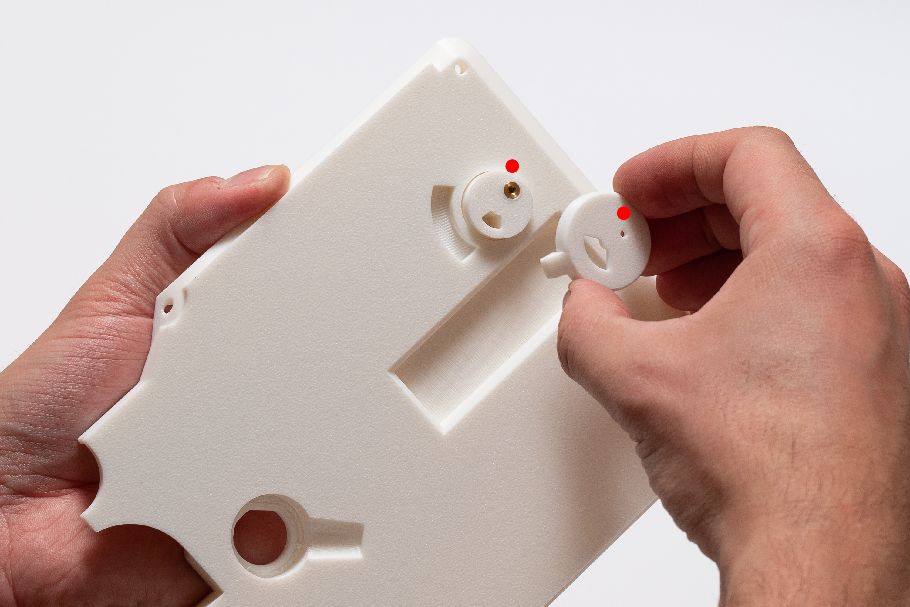
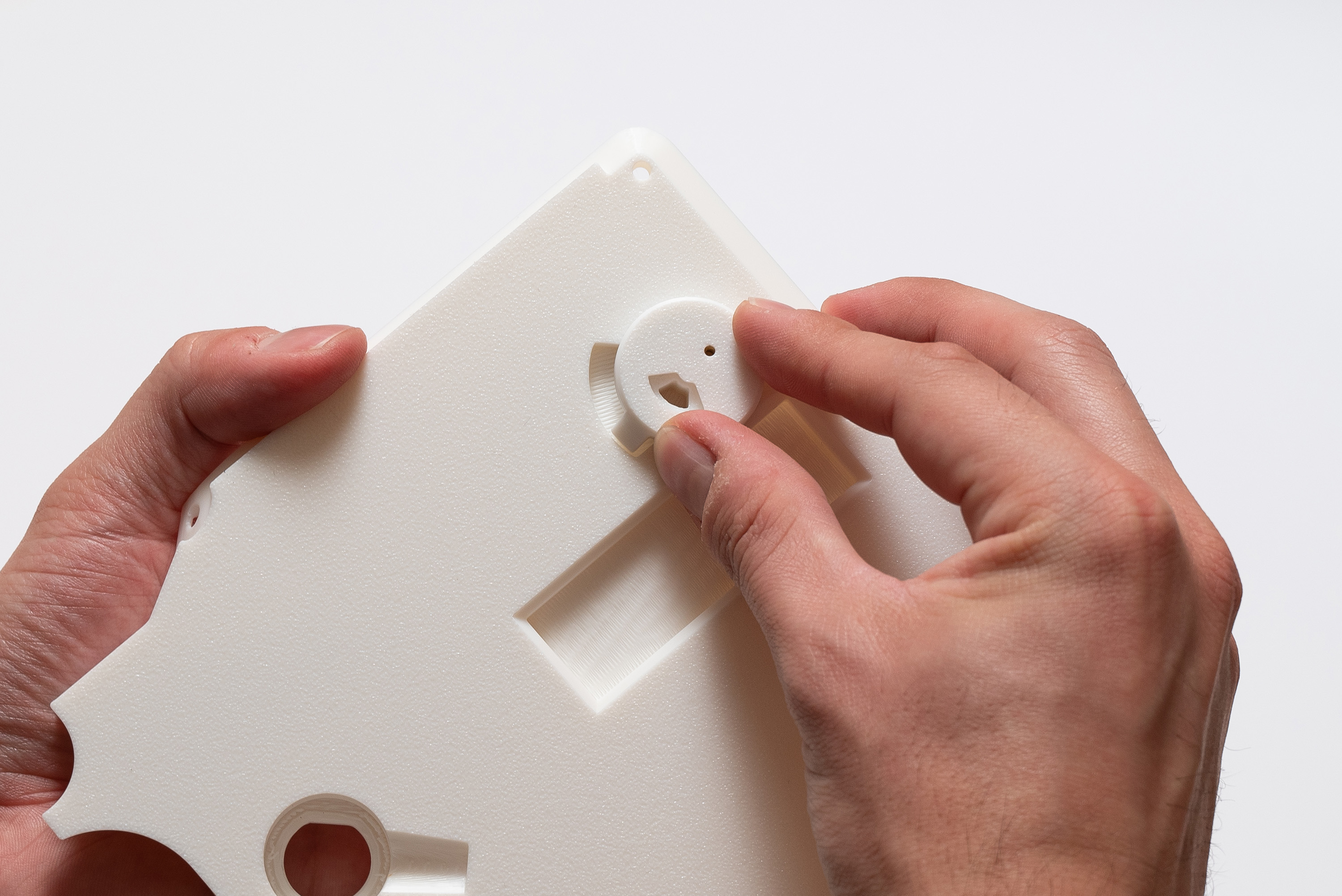
Place the switch_bottom into the middle piece, from below:
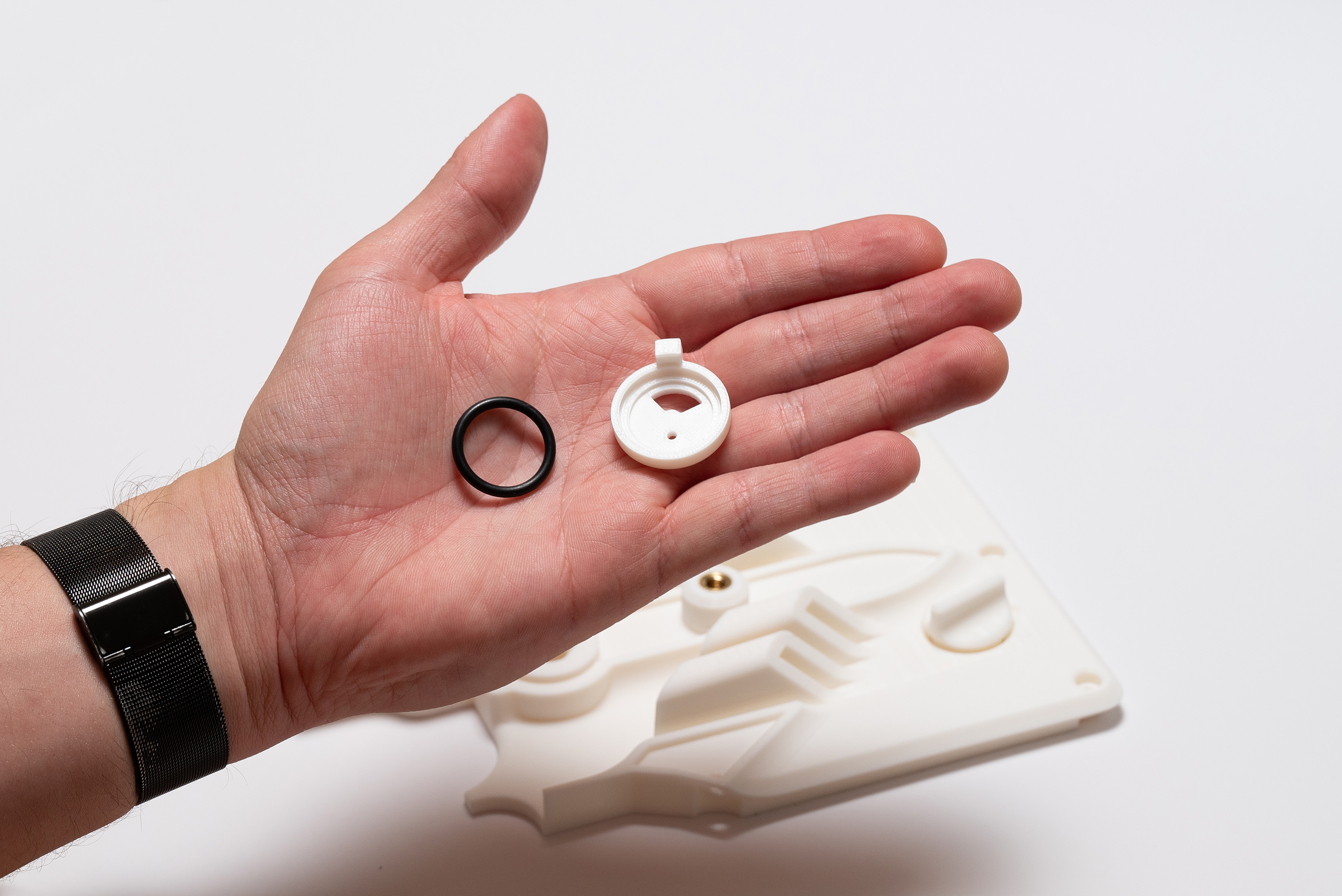
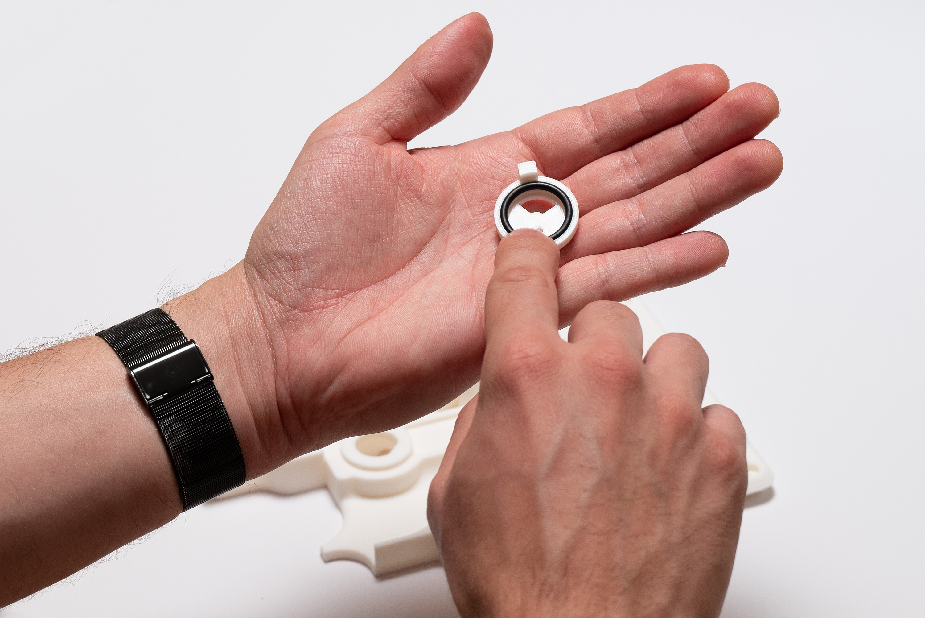
Insert the o-ring into the switch_top, observing if it is perfectly fitting into its recess:
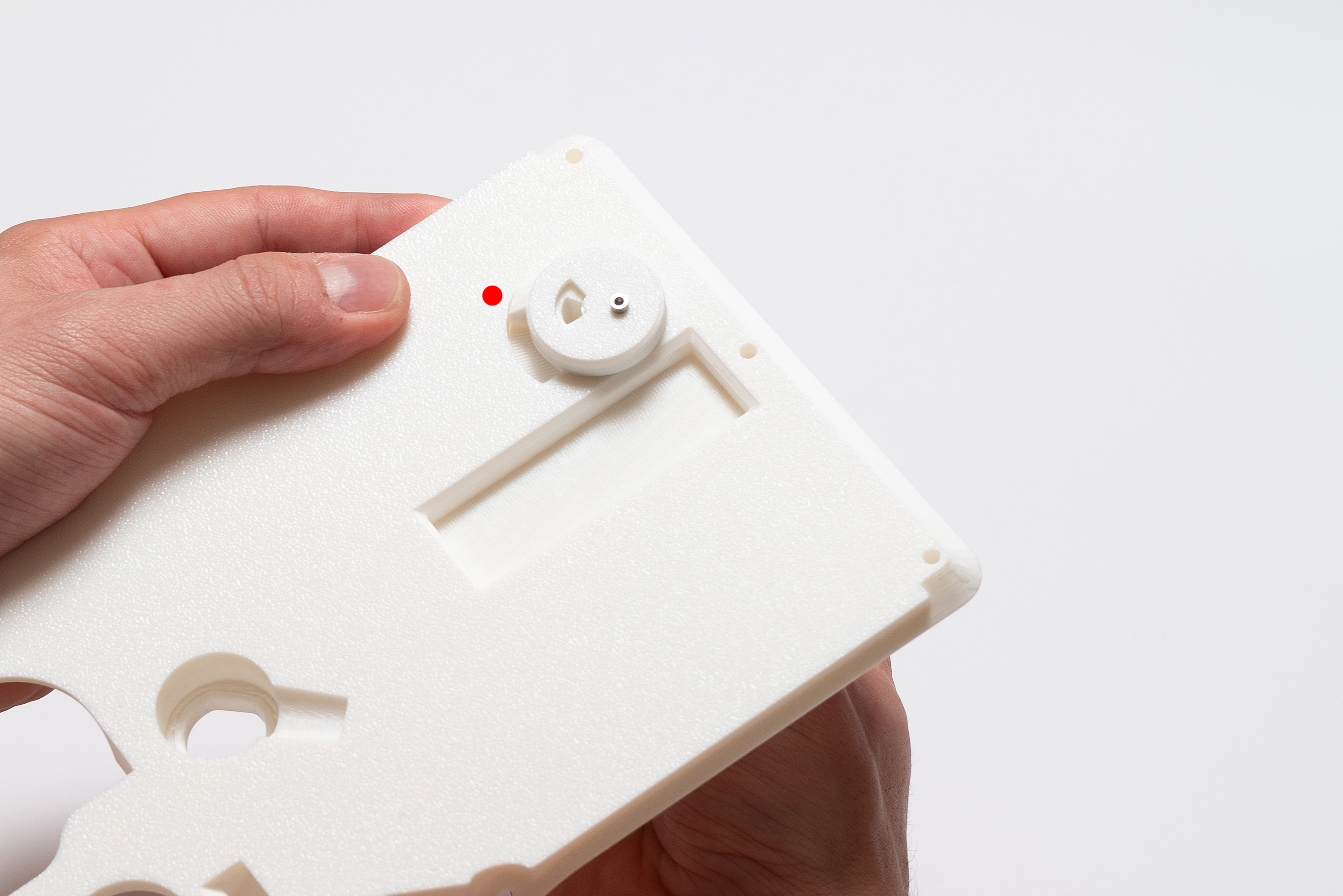
Align, then join the switch_top and switch_bottom with 1x M2X6 screw while keeping the middle piece in between:
✅ Result
The switch must move freely between start and end, but there should be no play between the three parts.
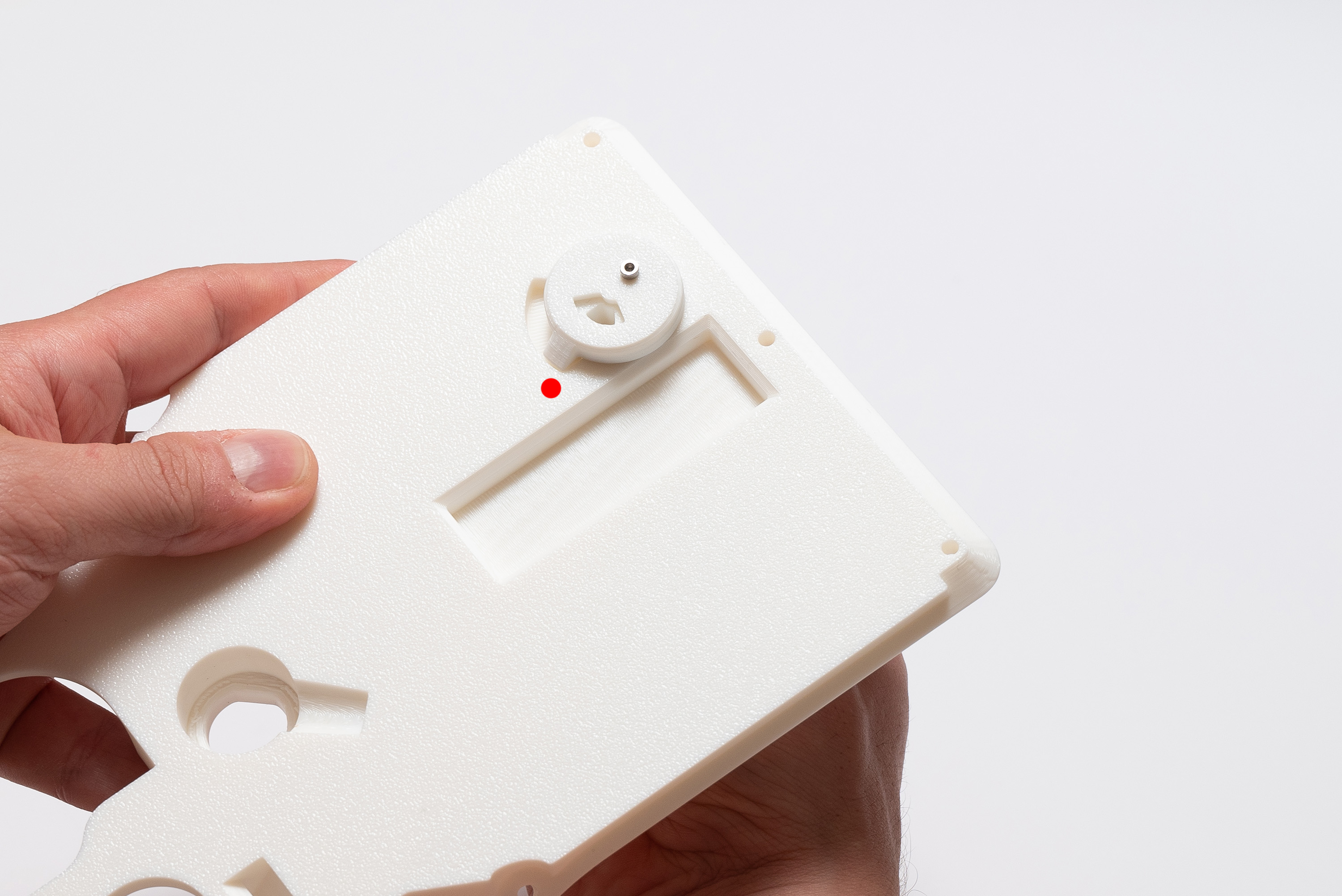
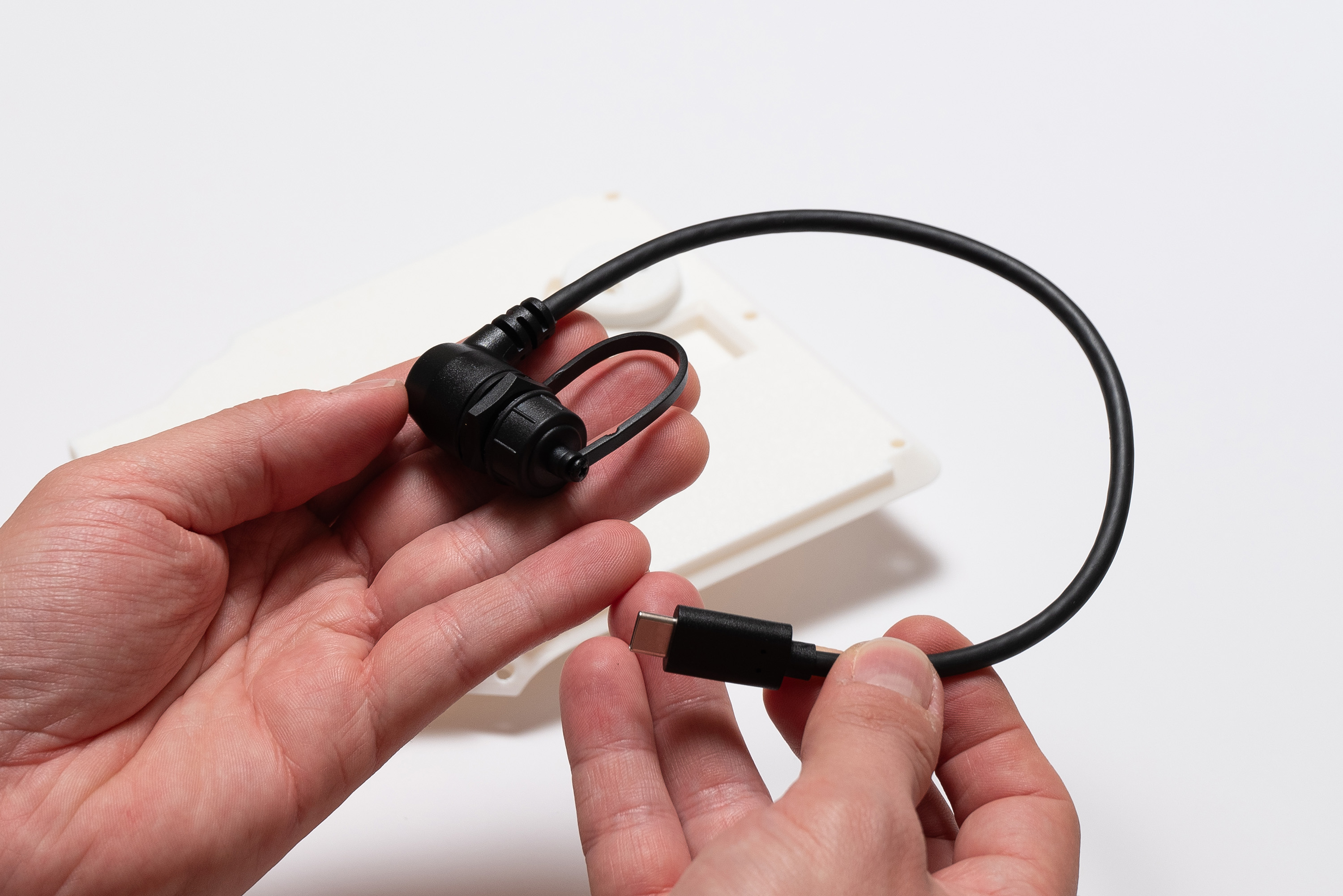
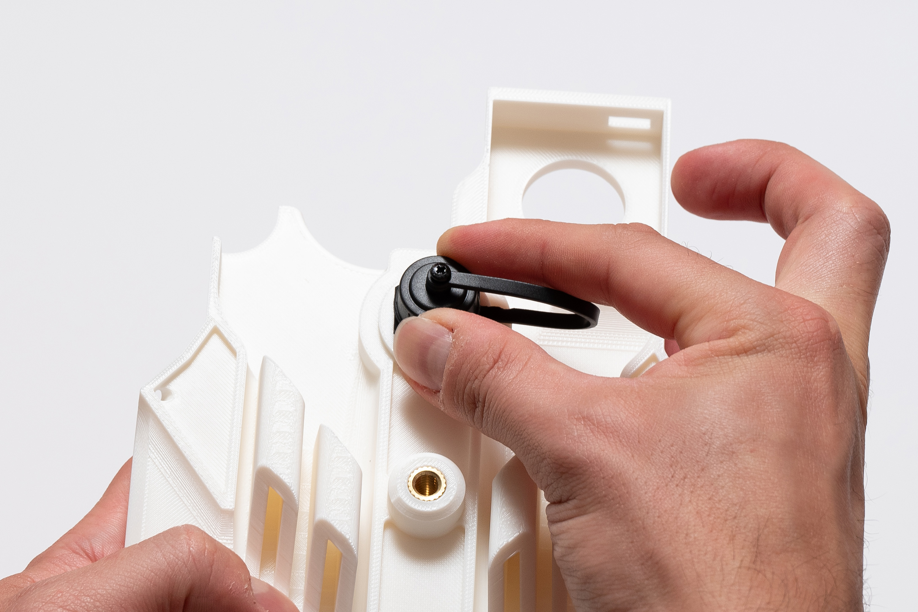
Step 16 – USB-C Cable
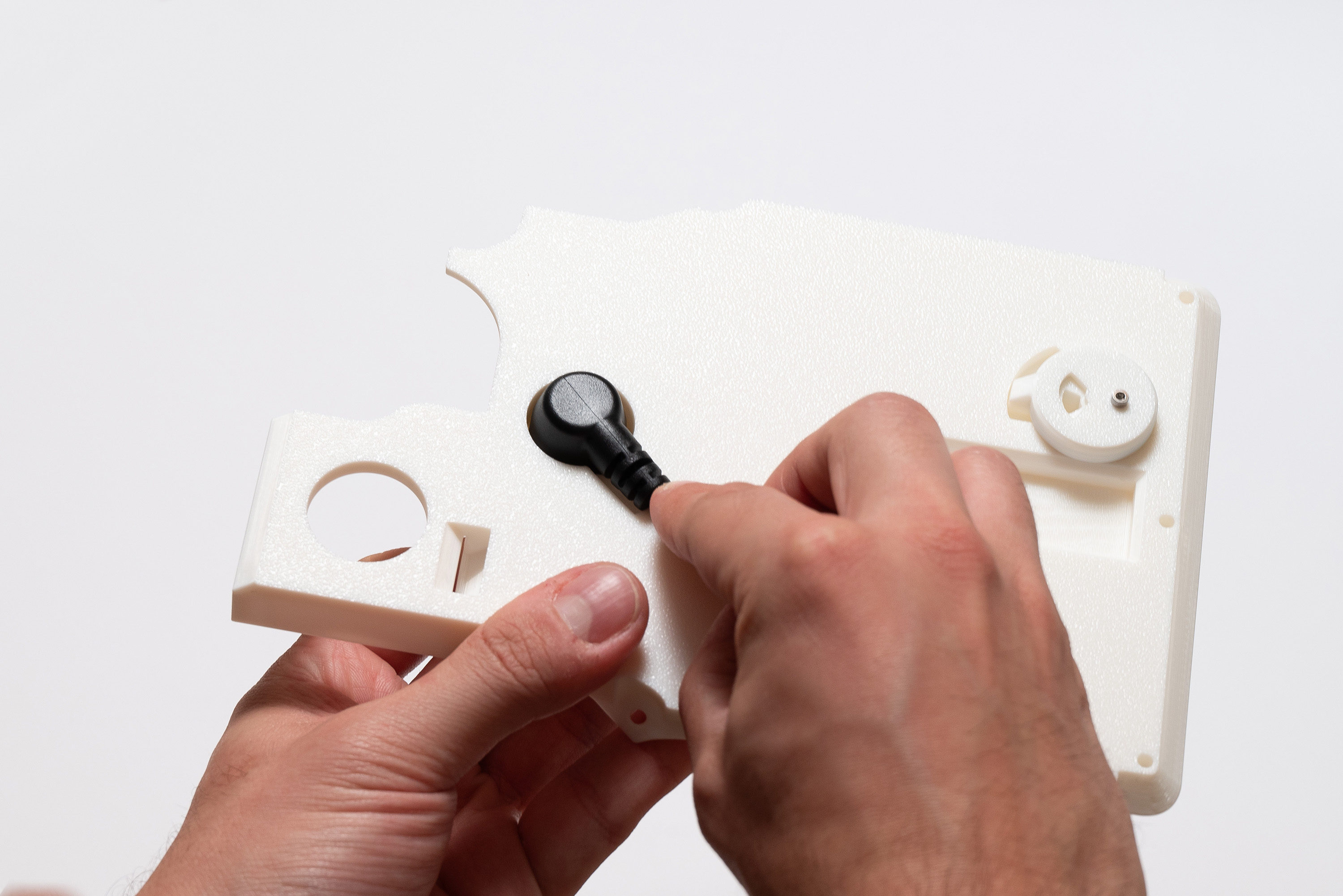
Pick the Waterproof USB-C cable:
Now, unscrew the cap and nut, remove them completely leaving the rubber seal, then put it back:
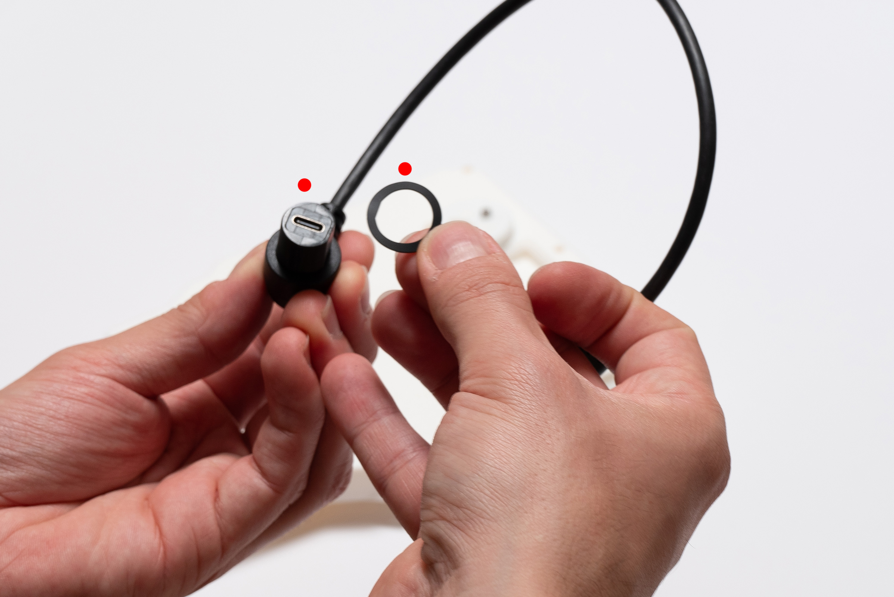
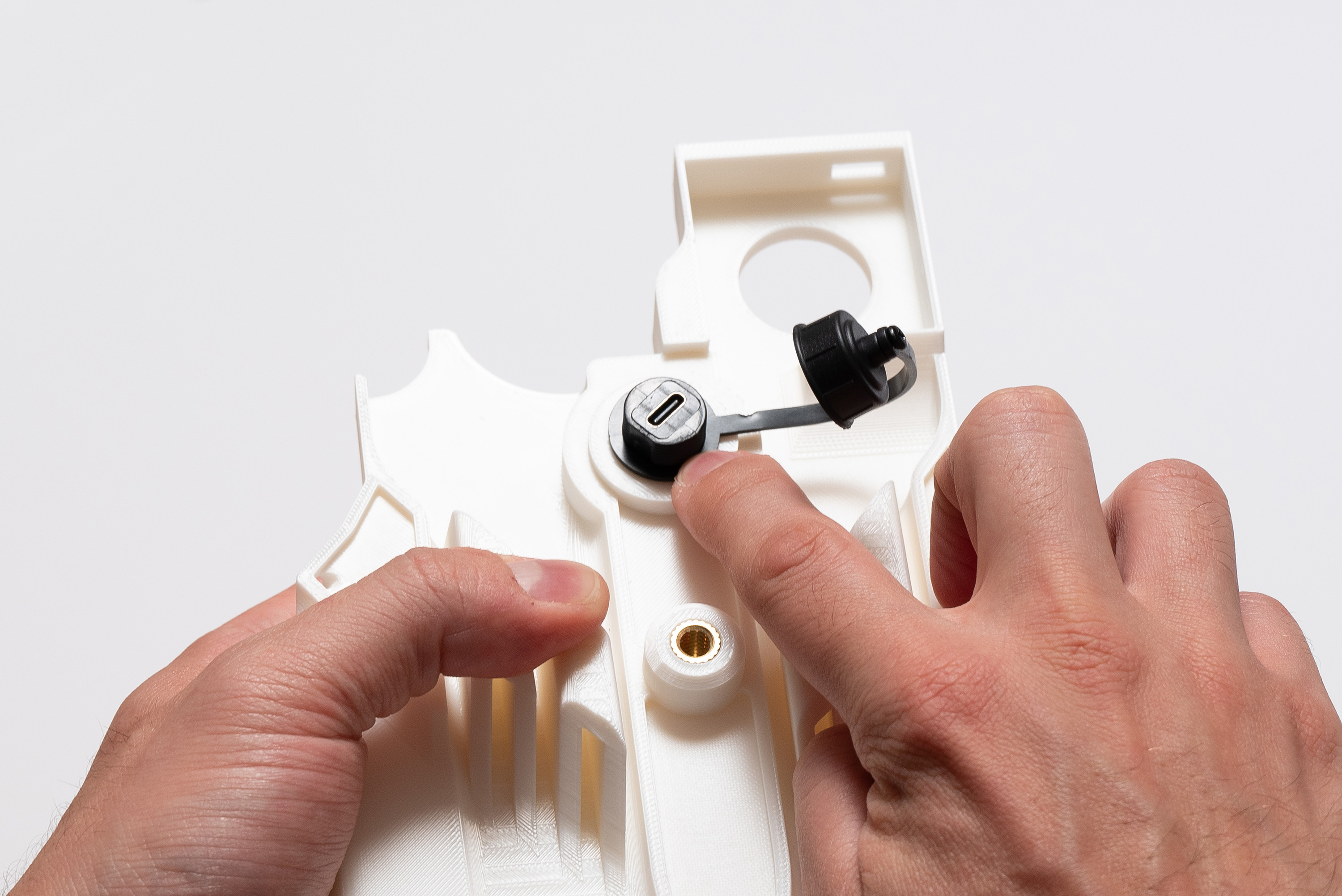
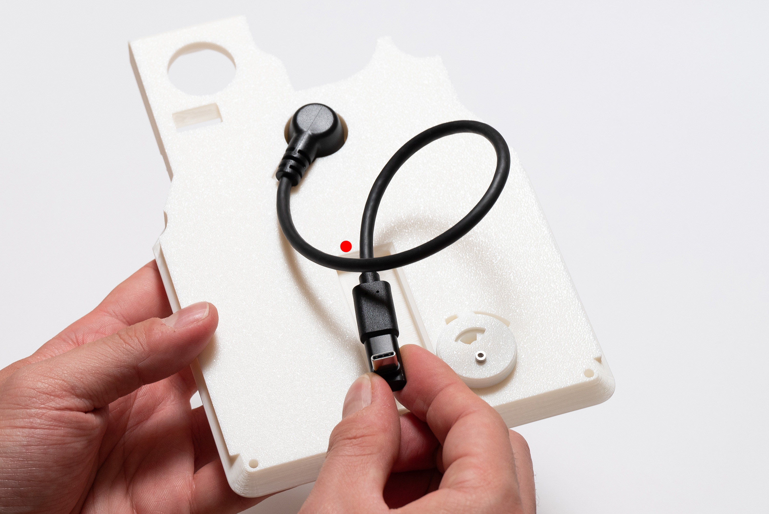
Place the cable in the appropriate place respecting the correct order of cable screw → rubber ring → middle piece:
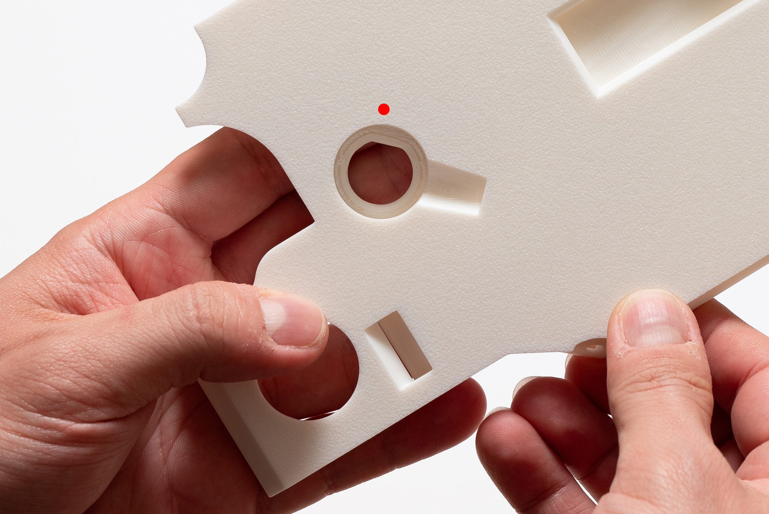
While holding everything together, turn the middle piece around and add the cap ring, leaving its strip pointing to the right.
Fasten the nut while keeping the cap strip at the same position:
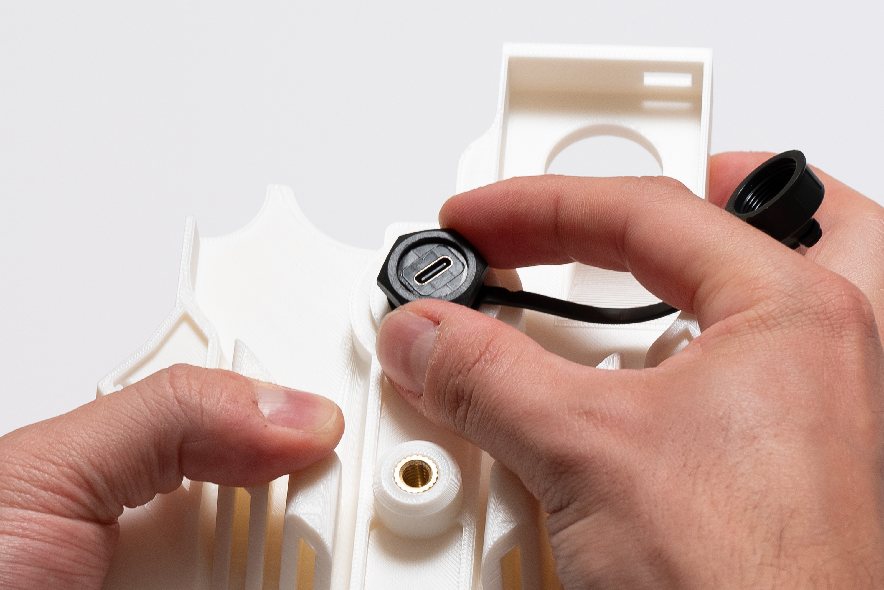
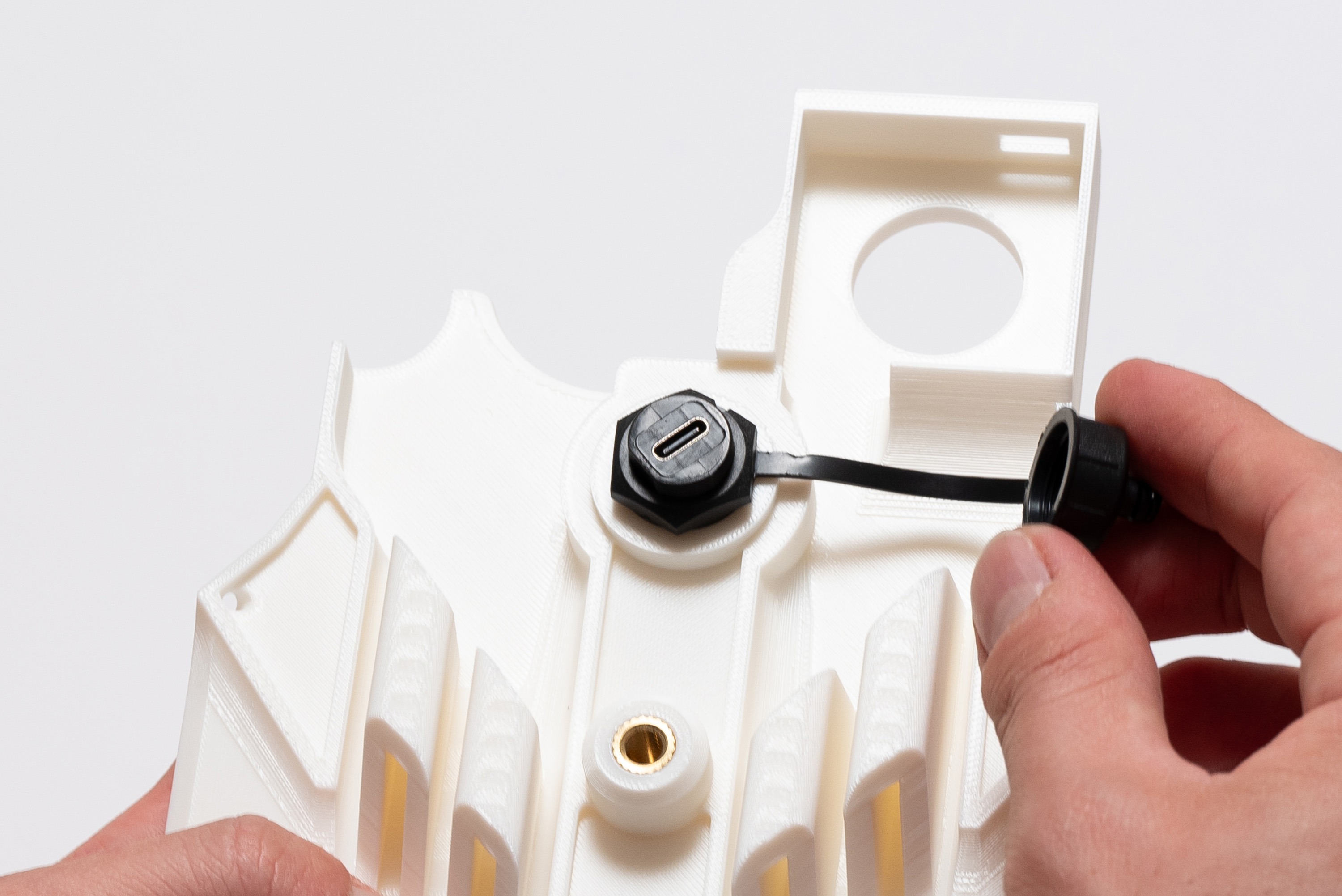
Screw the cap:
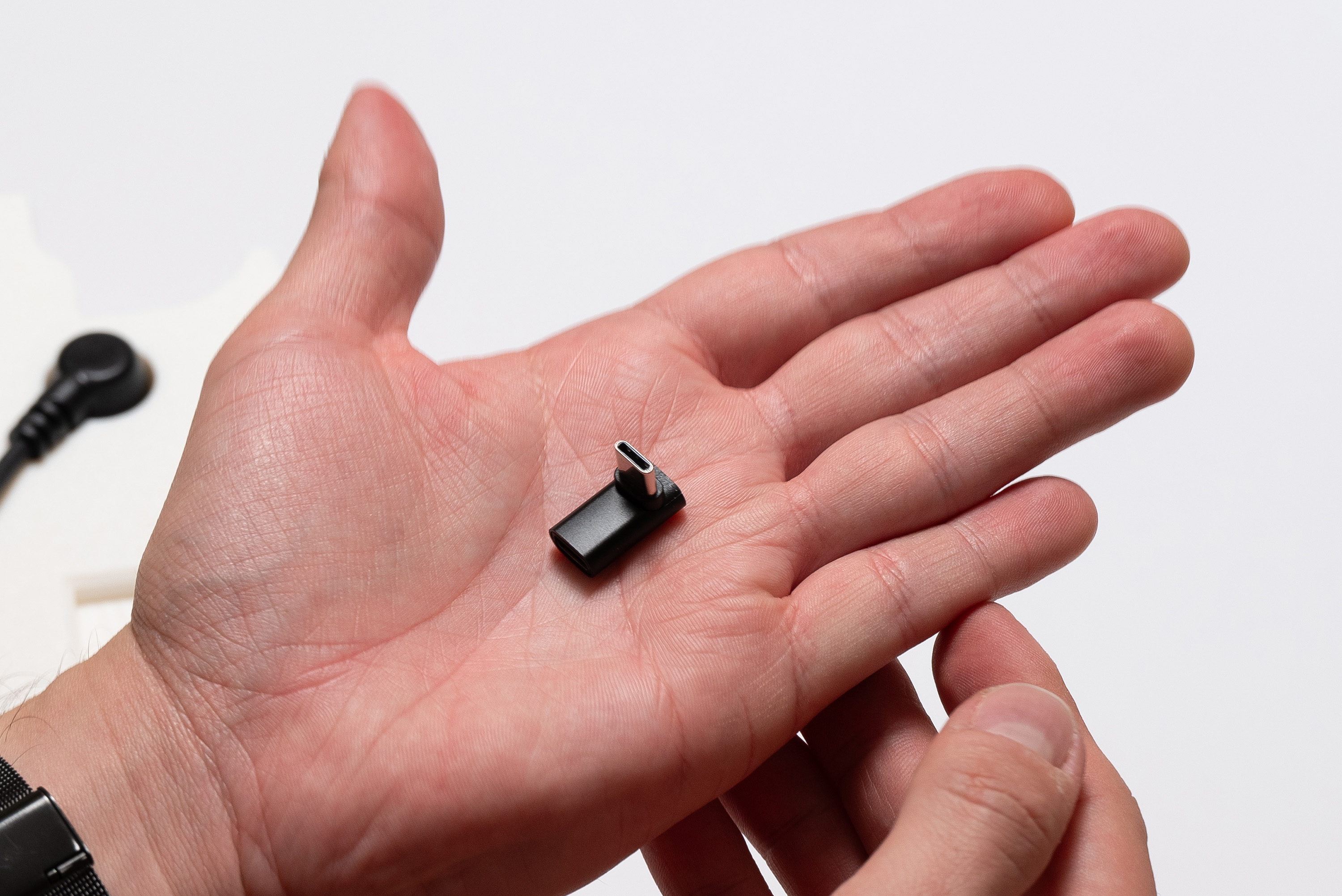
Connect the 90º USB-C adapter to the Waterproof USB-C cable:
Twist the cable as indicated to help avoiding collision with other parts when finishing the assembly:
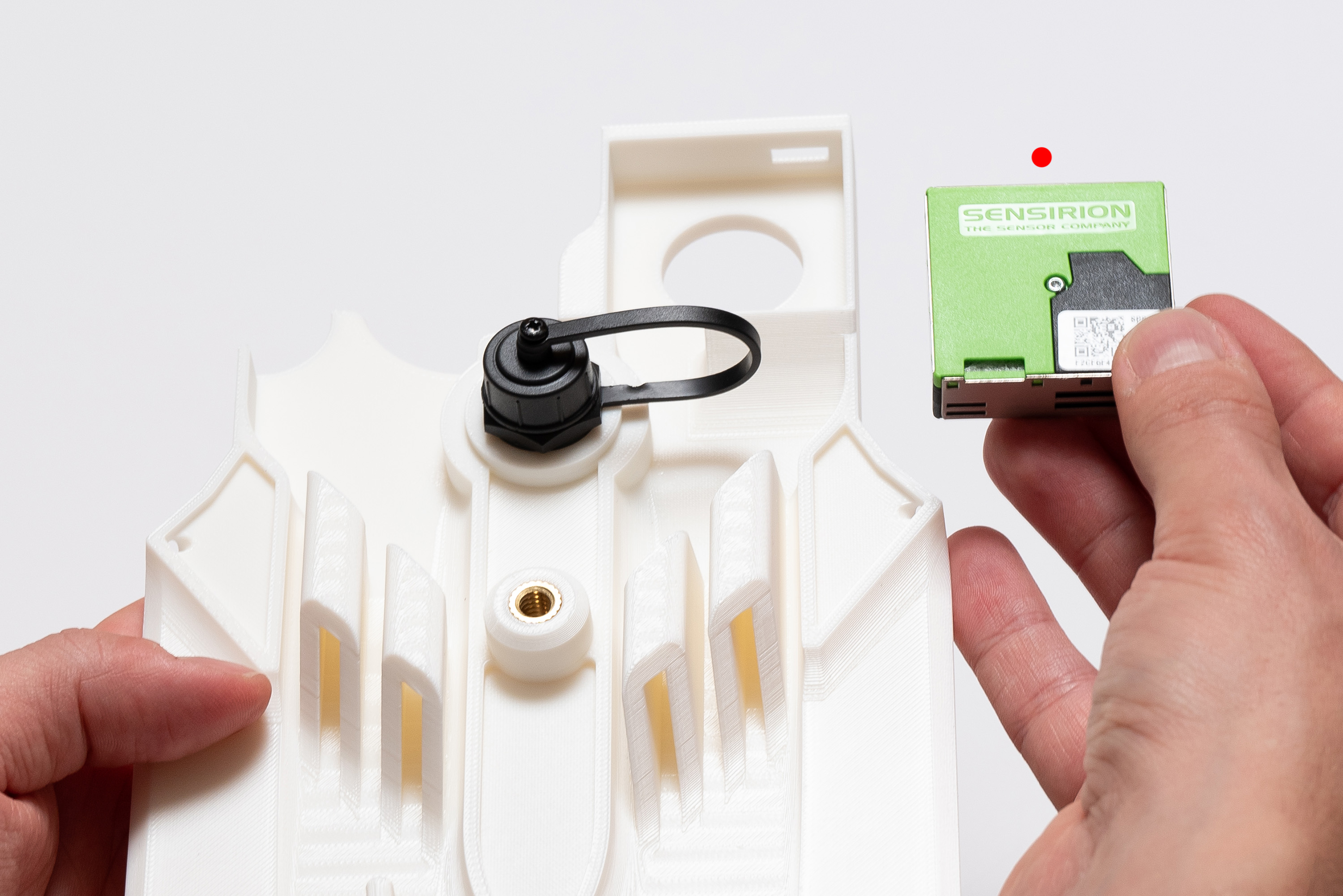
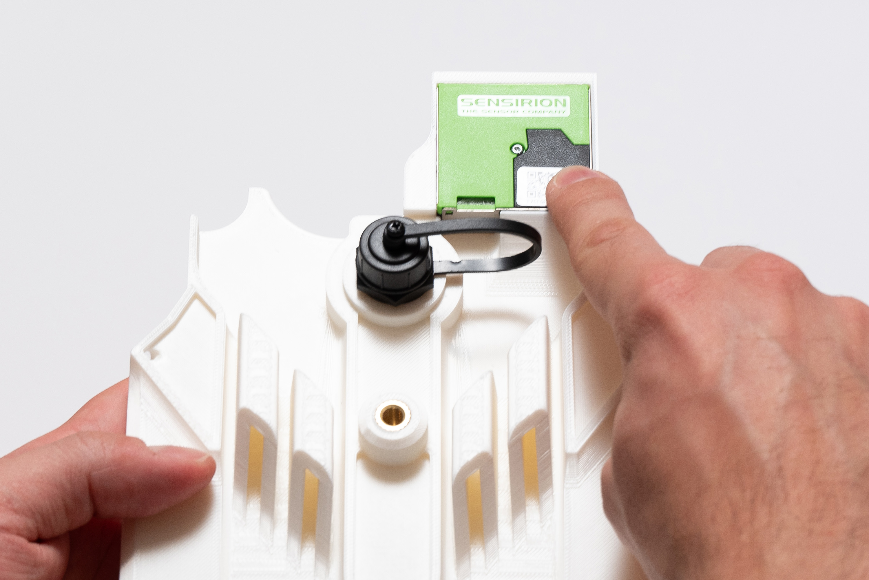
Step 17 – Particulate Sensor
Pay attention to the correct orientation, since there are several ways for assembling it wrong.
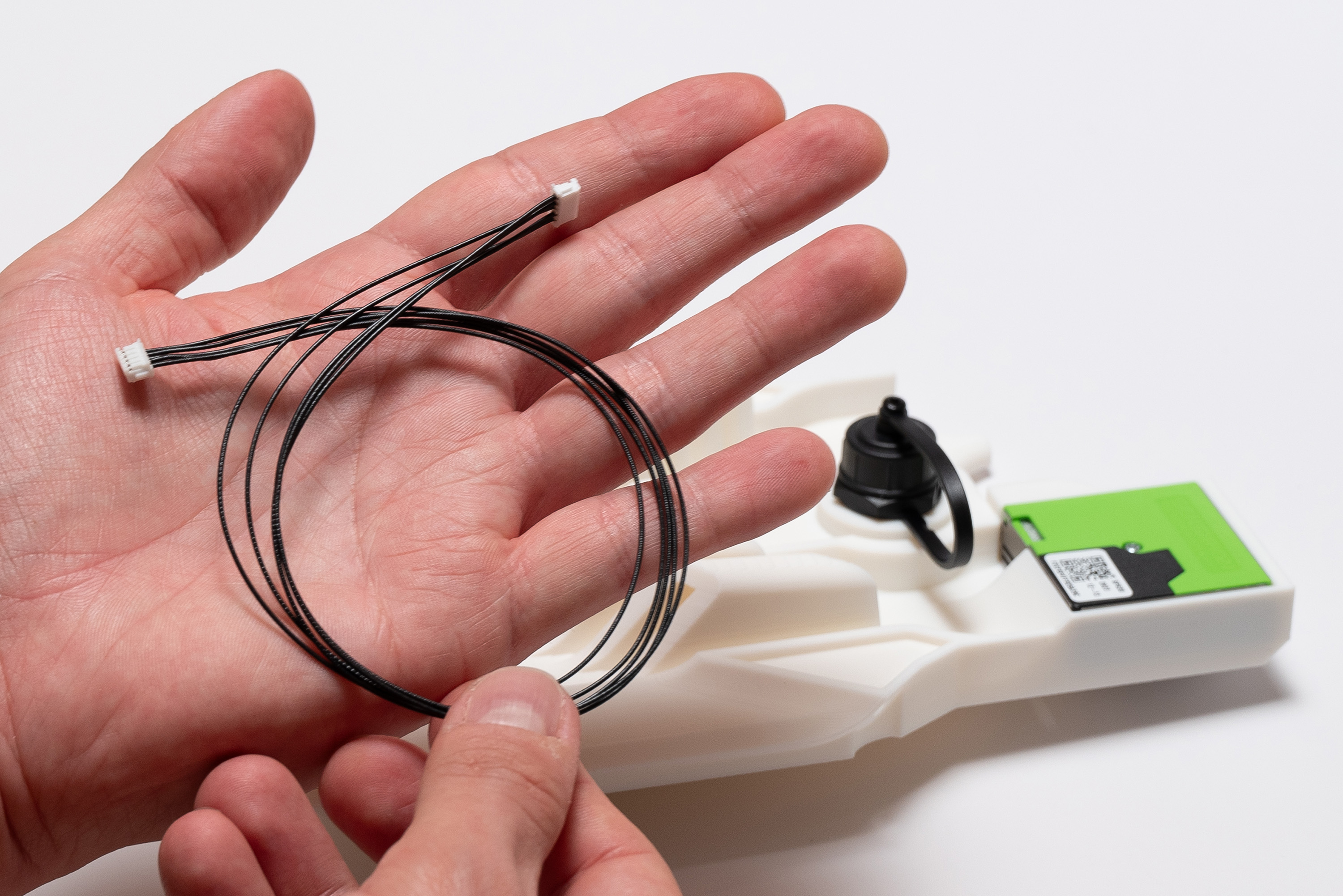
Place the Sensirion sensor into its craddle on the middle piece:
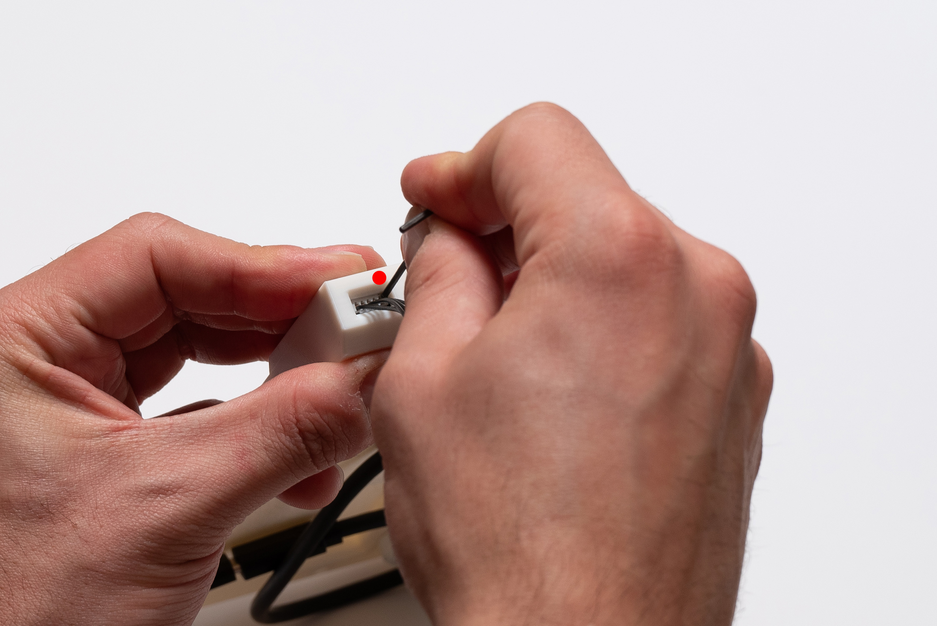
Attach the cable to the Sensirion sensor:
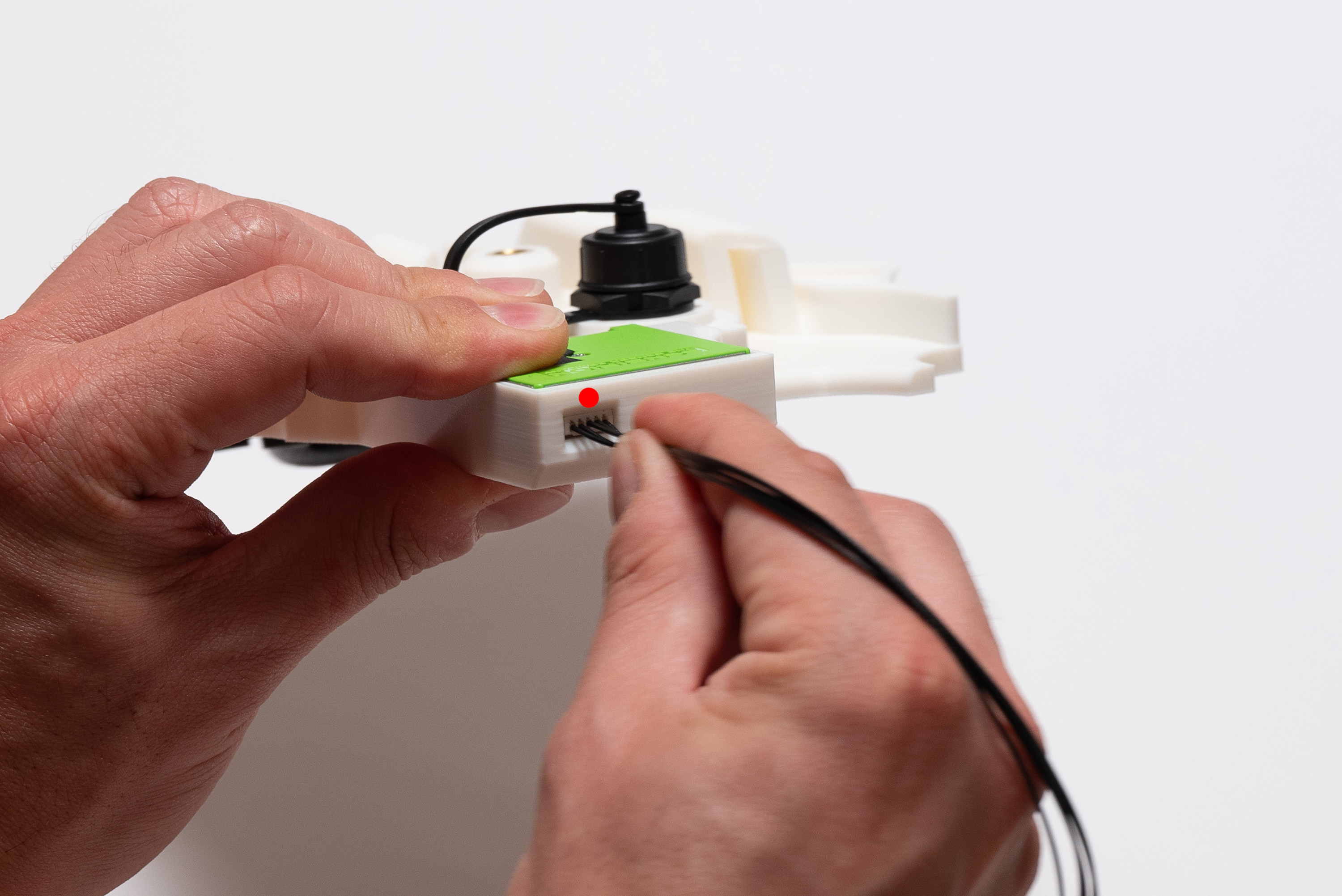
If you need, use a tweezer or screwdriver to help attaching the sensor properly to the end.
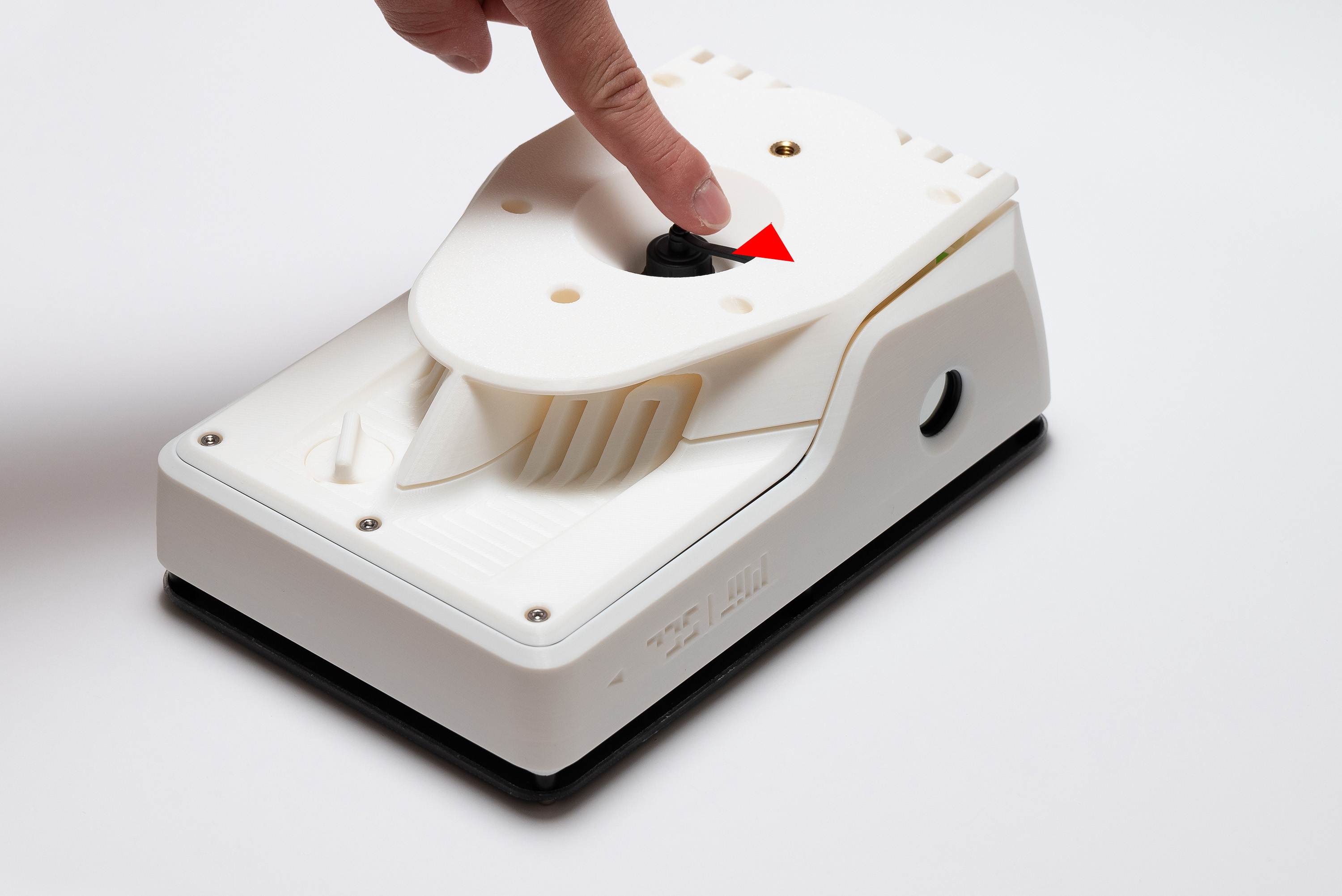
To allow for the middle piece to be attached to the top piece correctly, align the switch longitudinally ("on" position):
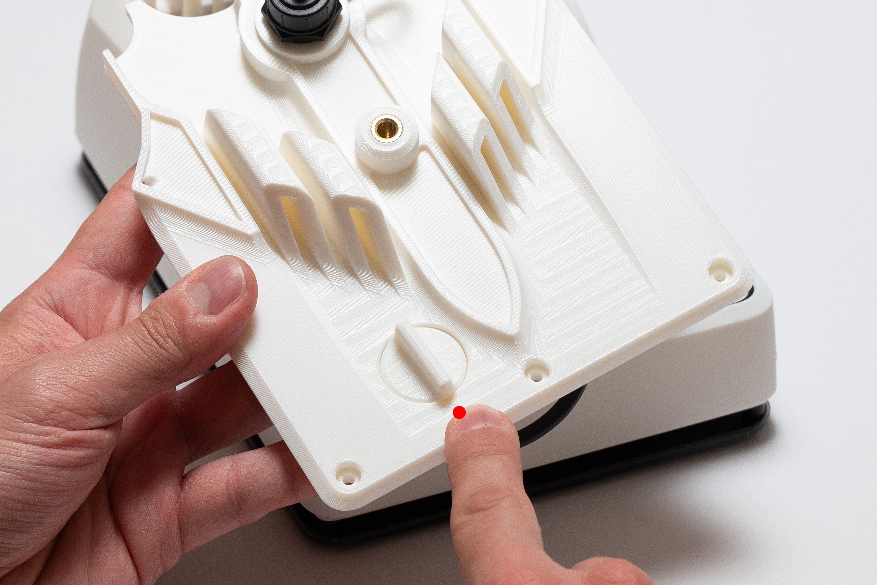
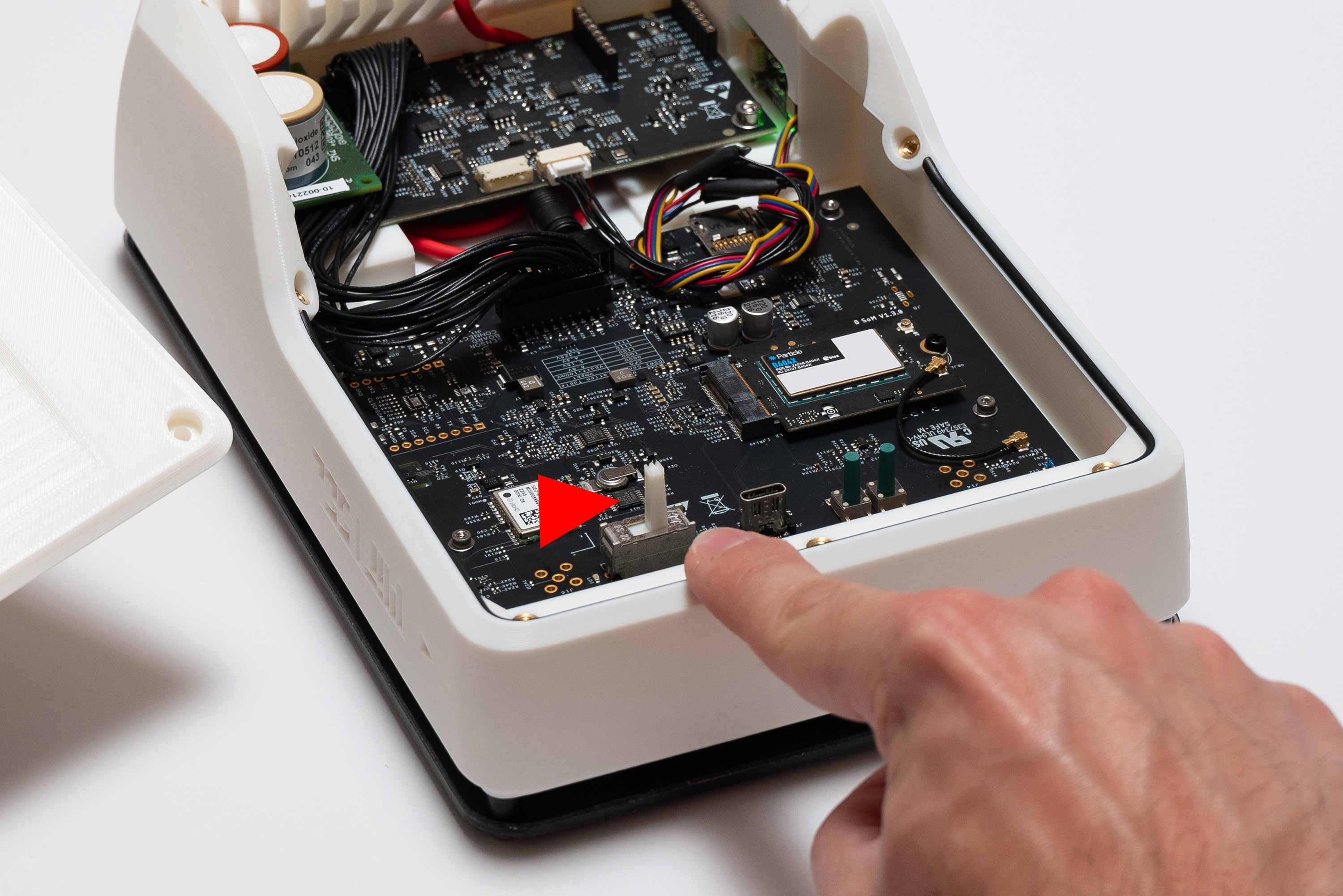
And push the Main Board switch to the right ("on" position):
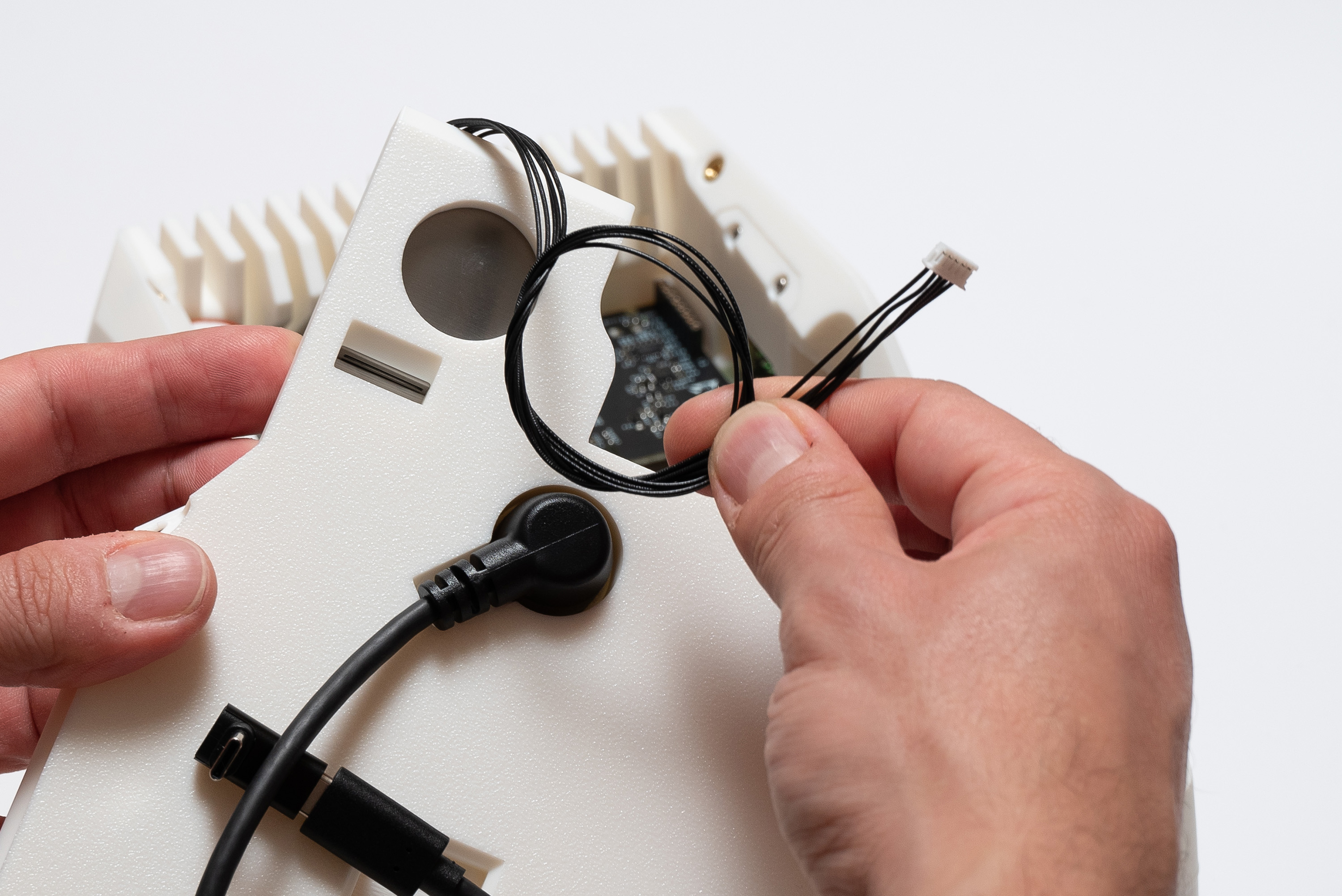
Roll the Sensirion cable to remove the excess and connect it to the indicate spot:
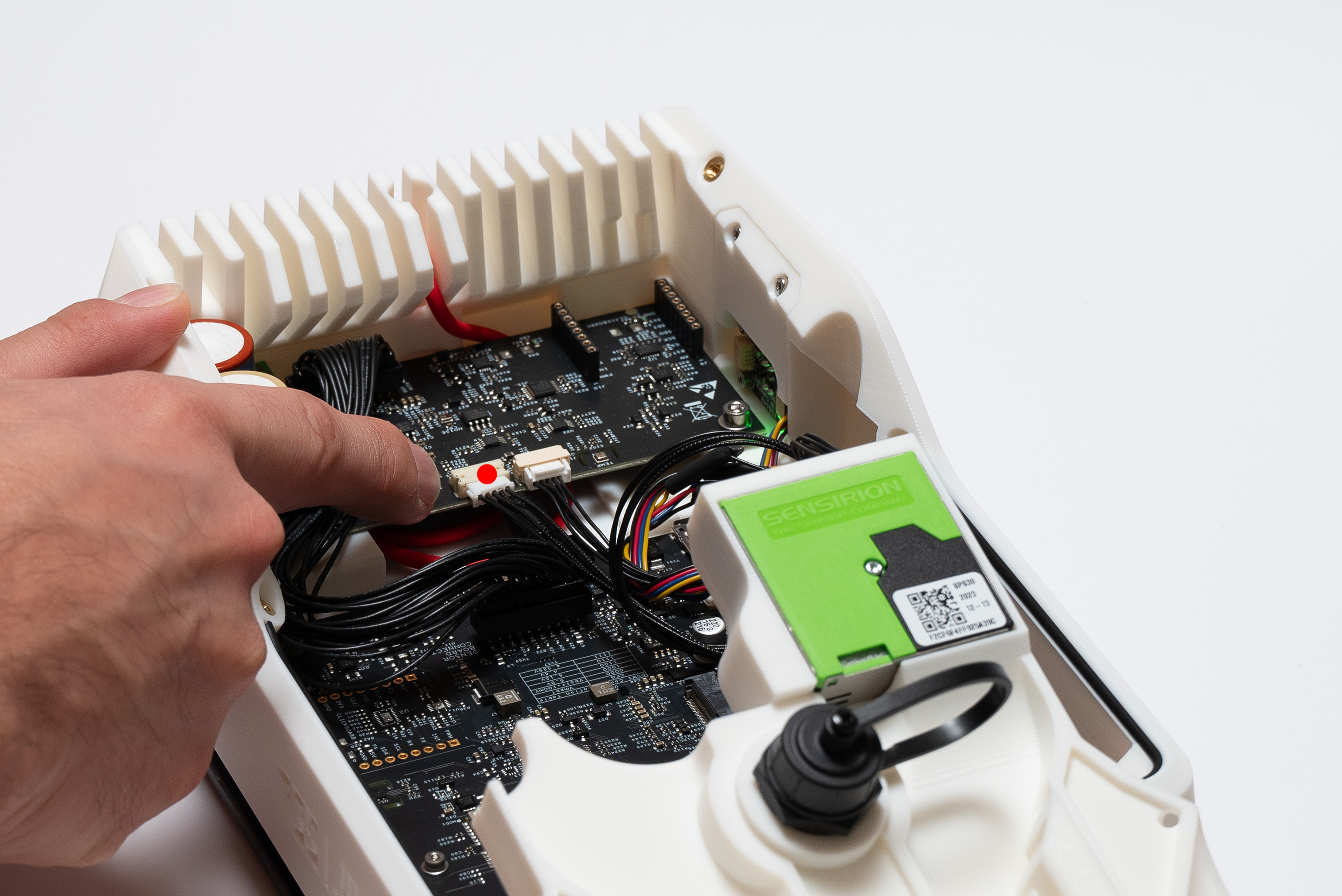
✅ Result
Step 18 – Closing
Connect the 90º USB-C Adapter to the Main Board:
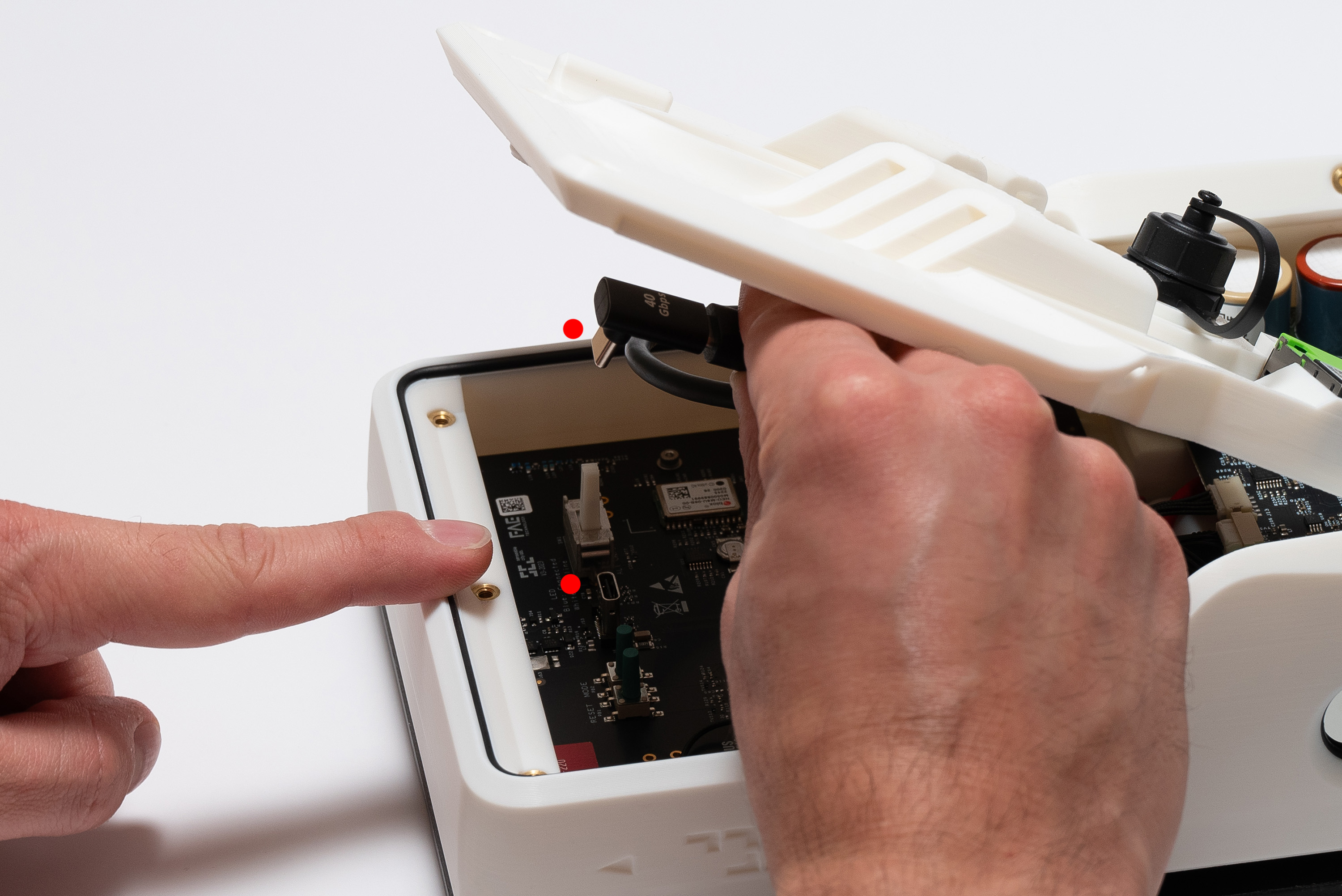
With care, align the middle and top pieces together while respecting the switch position:
Now you must move back the switch counter-clockwise to turn the device off.
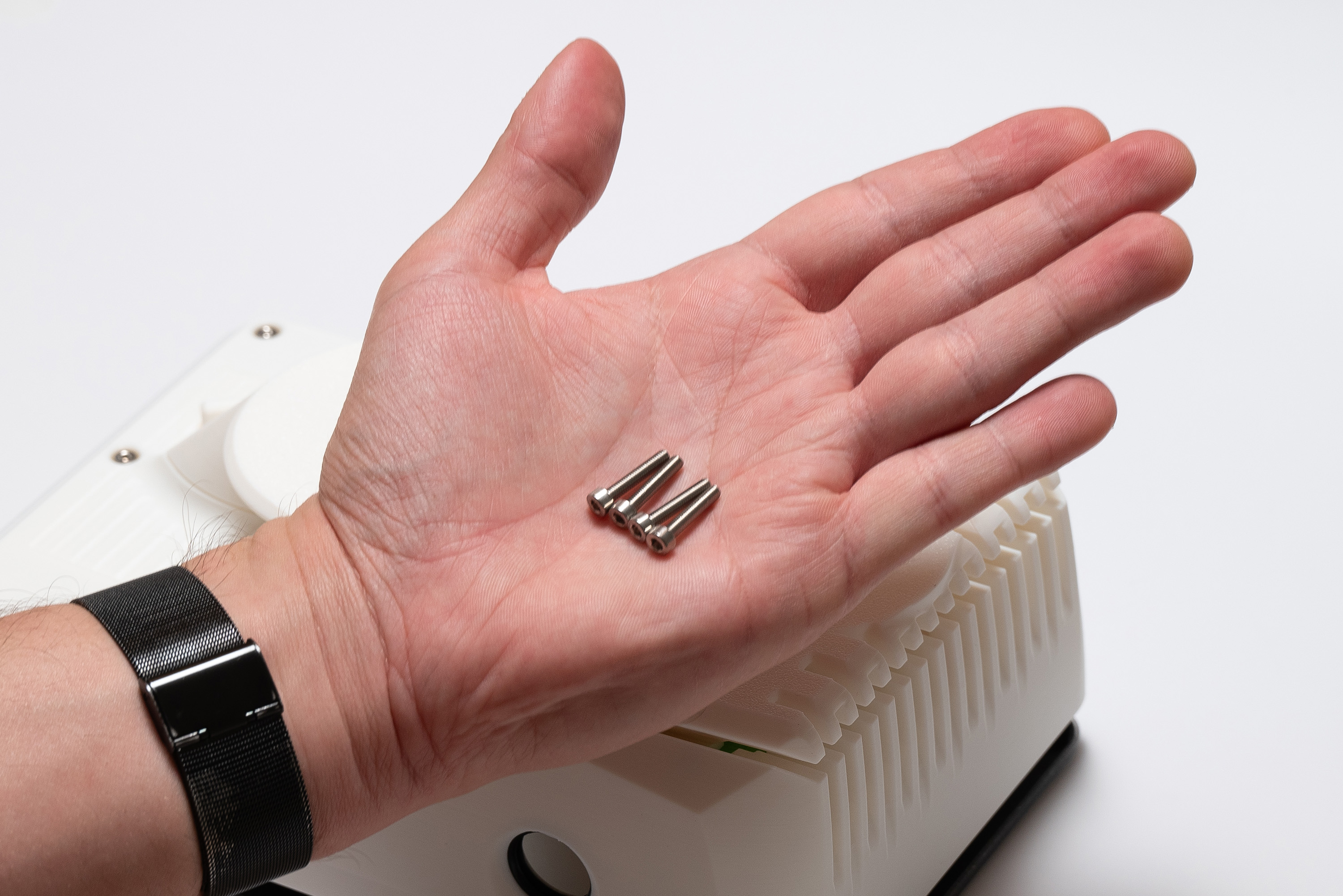
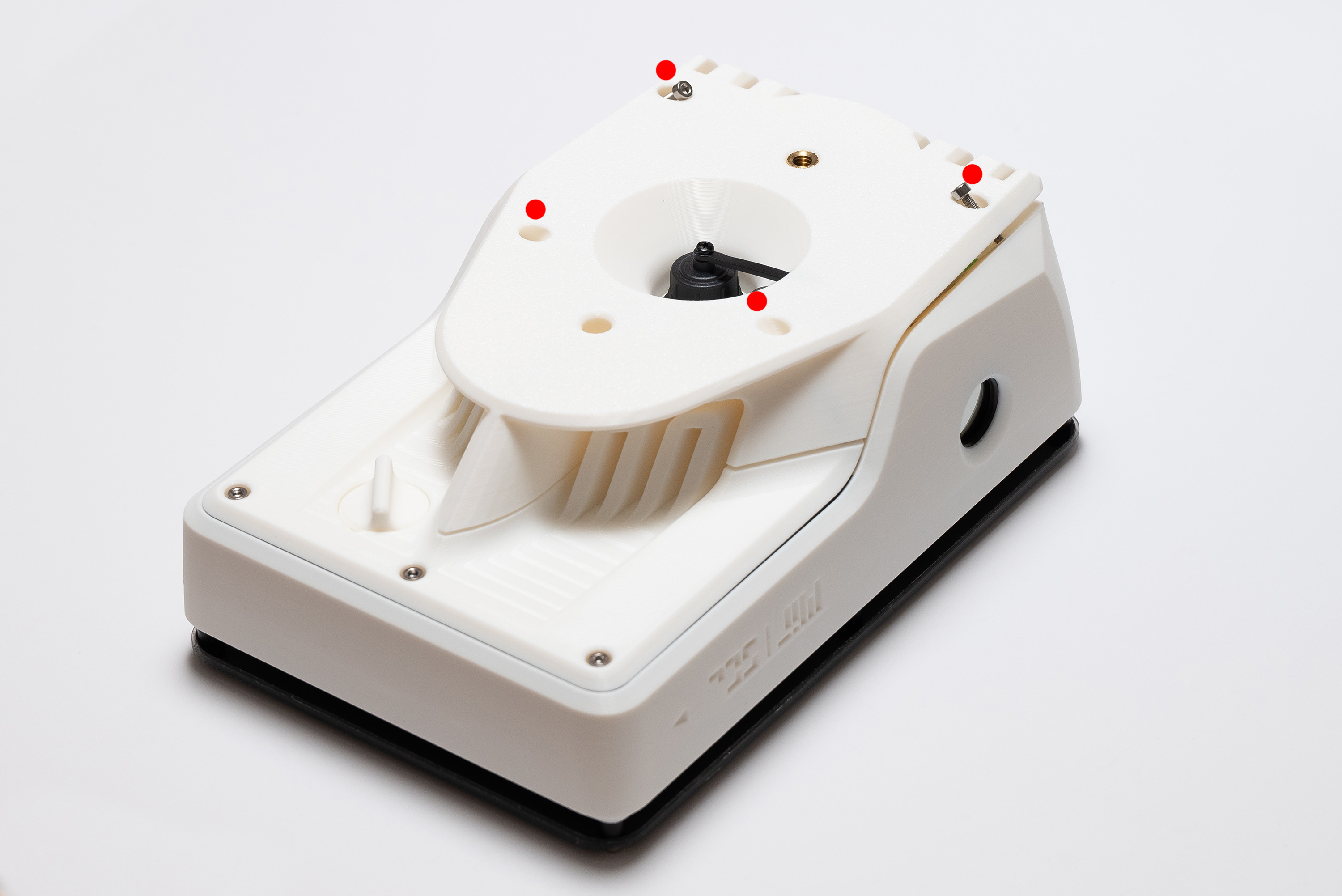
Fasten 3x M3x16 screws, joining the middle and top pieces together:
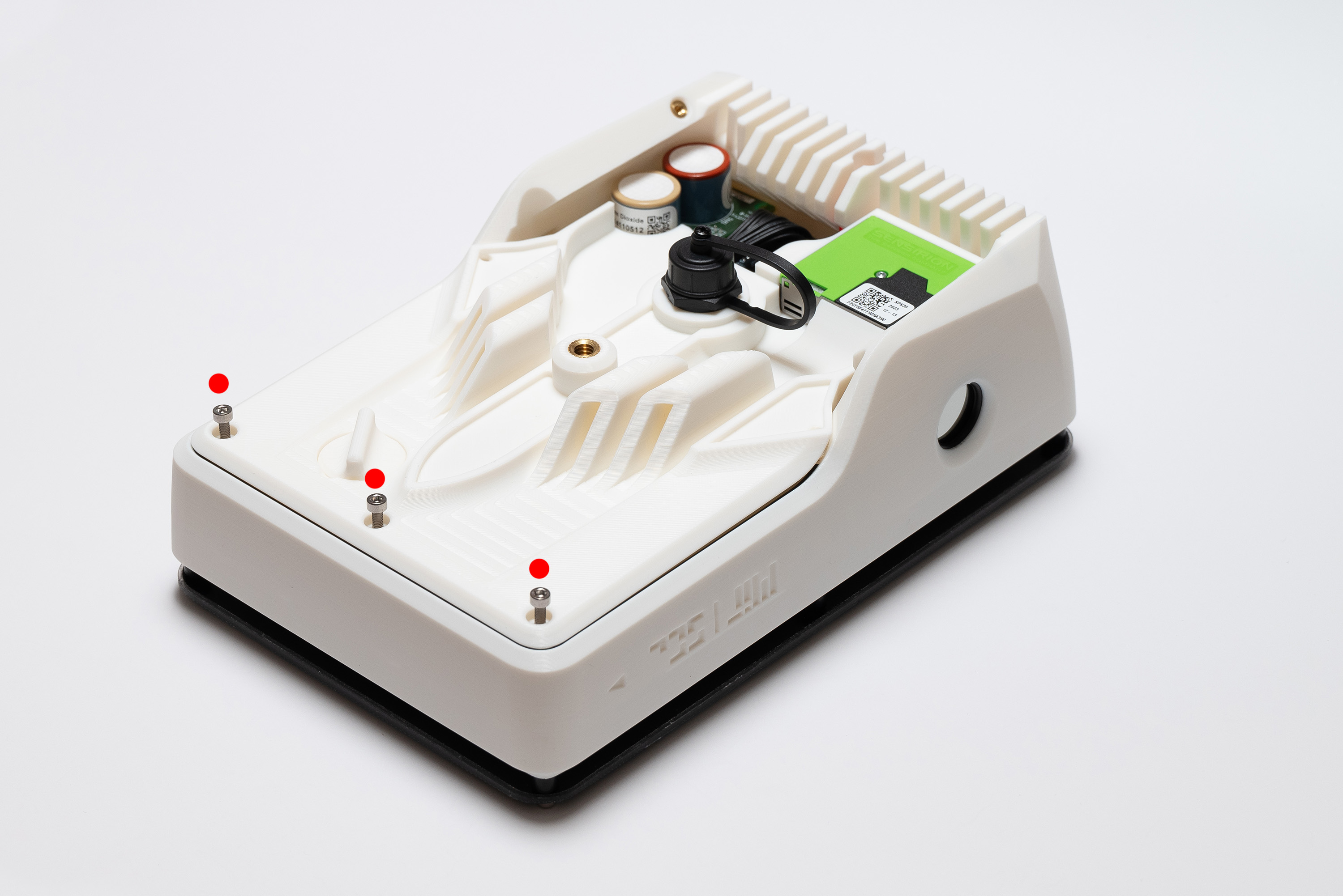
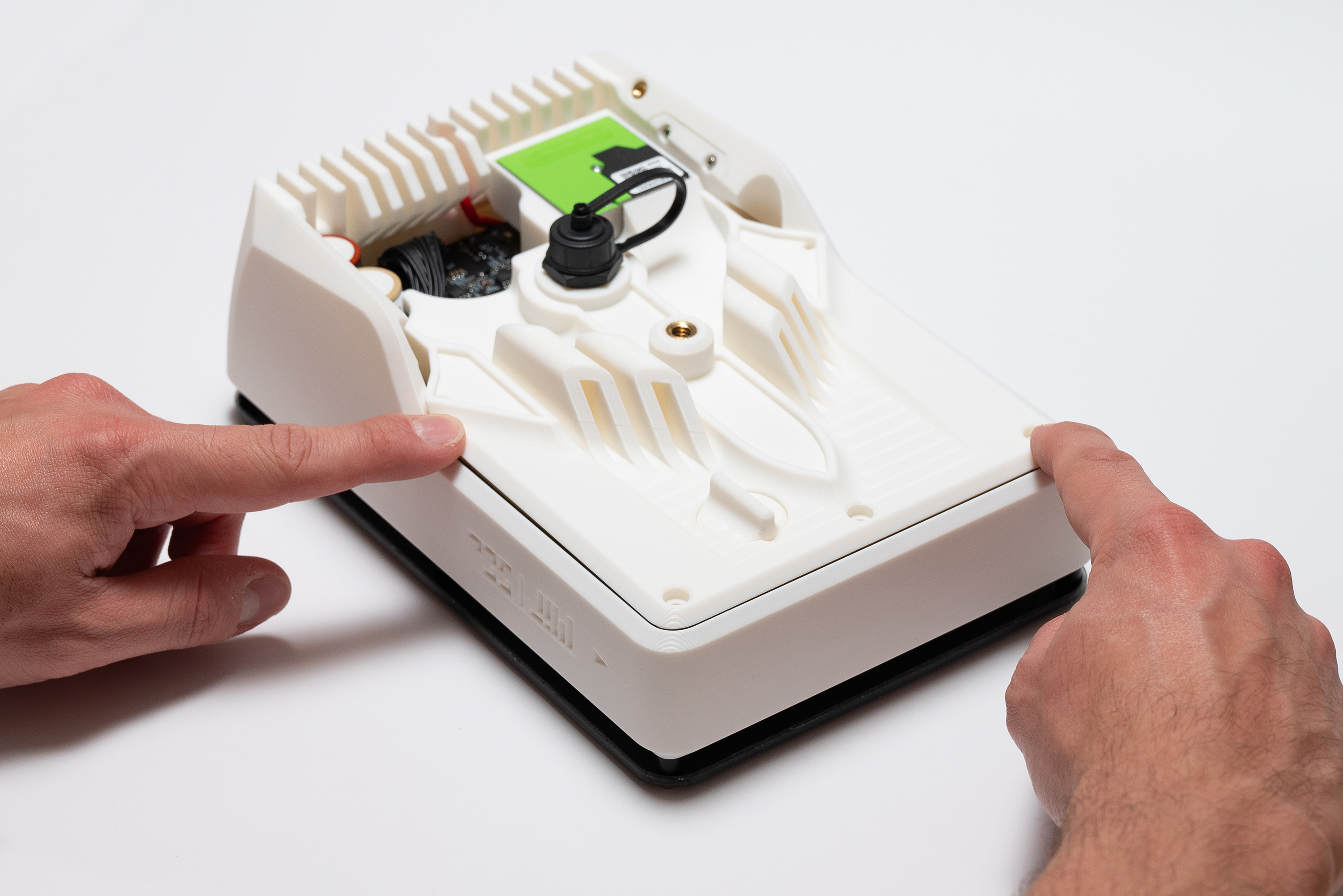
Position the bottom piece over the top and middle pieces:
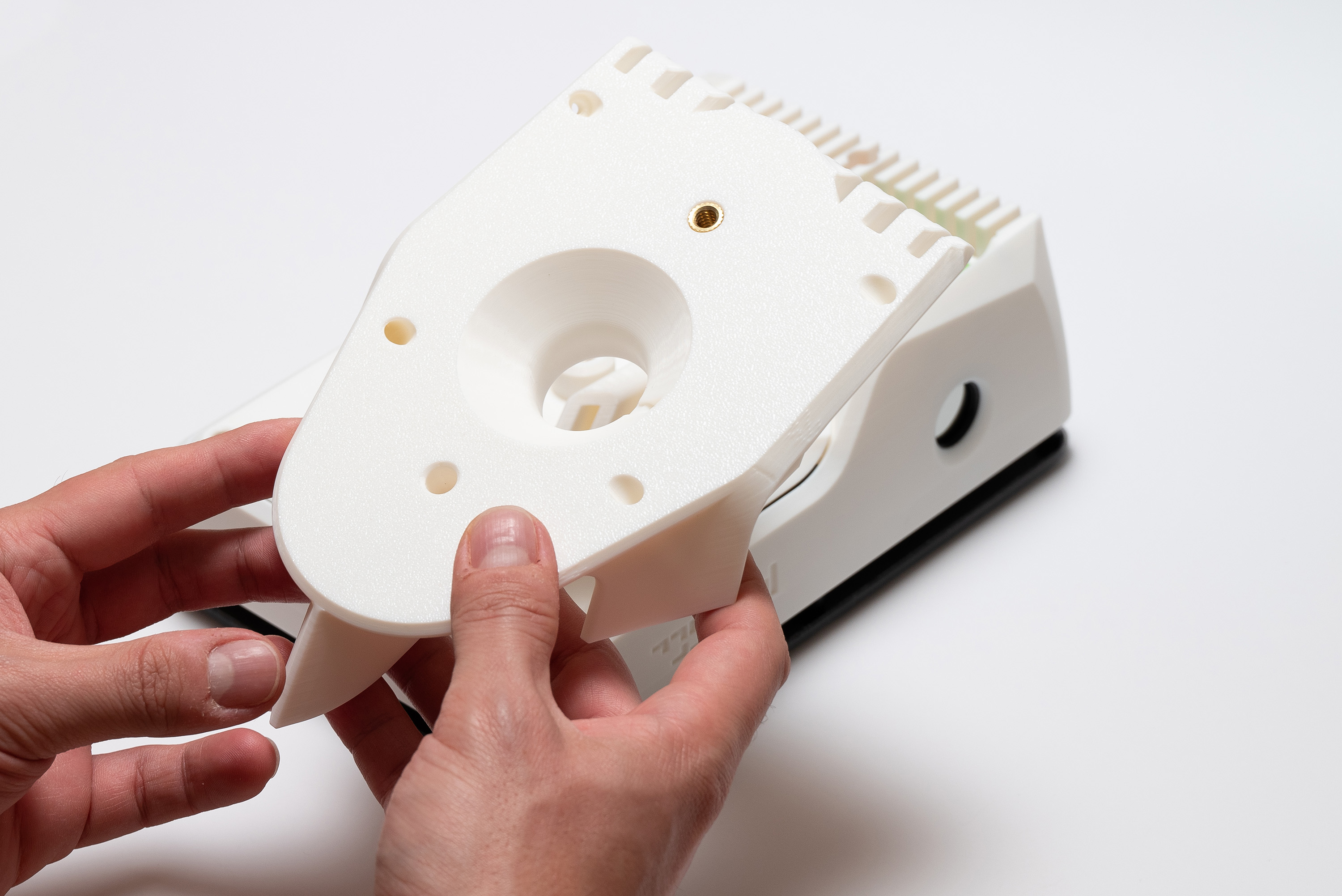
Keep the cap strip out of the way:
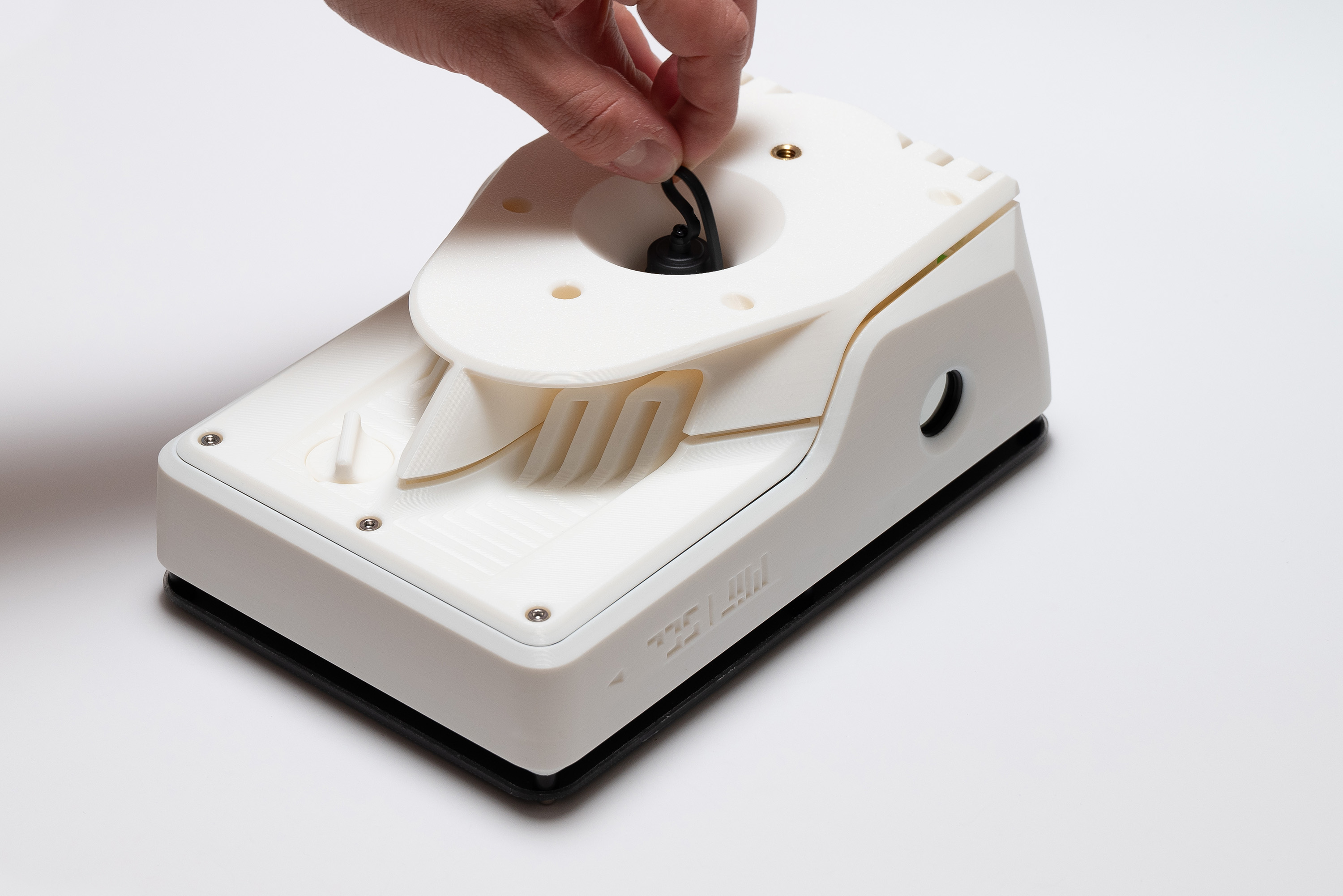
Then insert it into the appropriate entrance on the right:
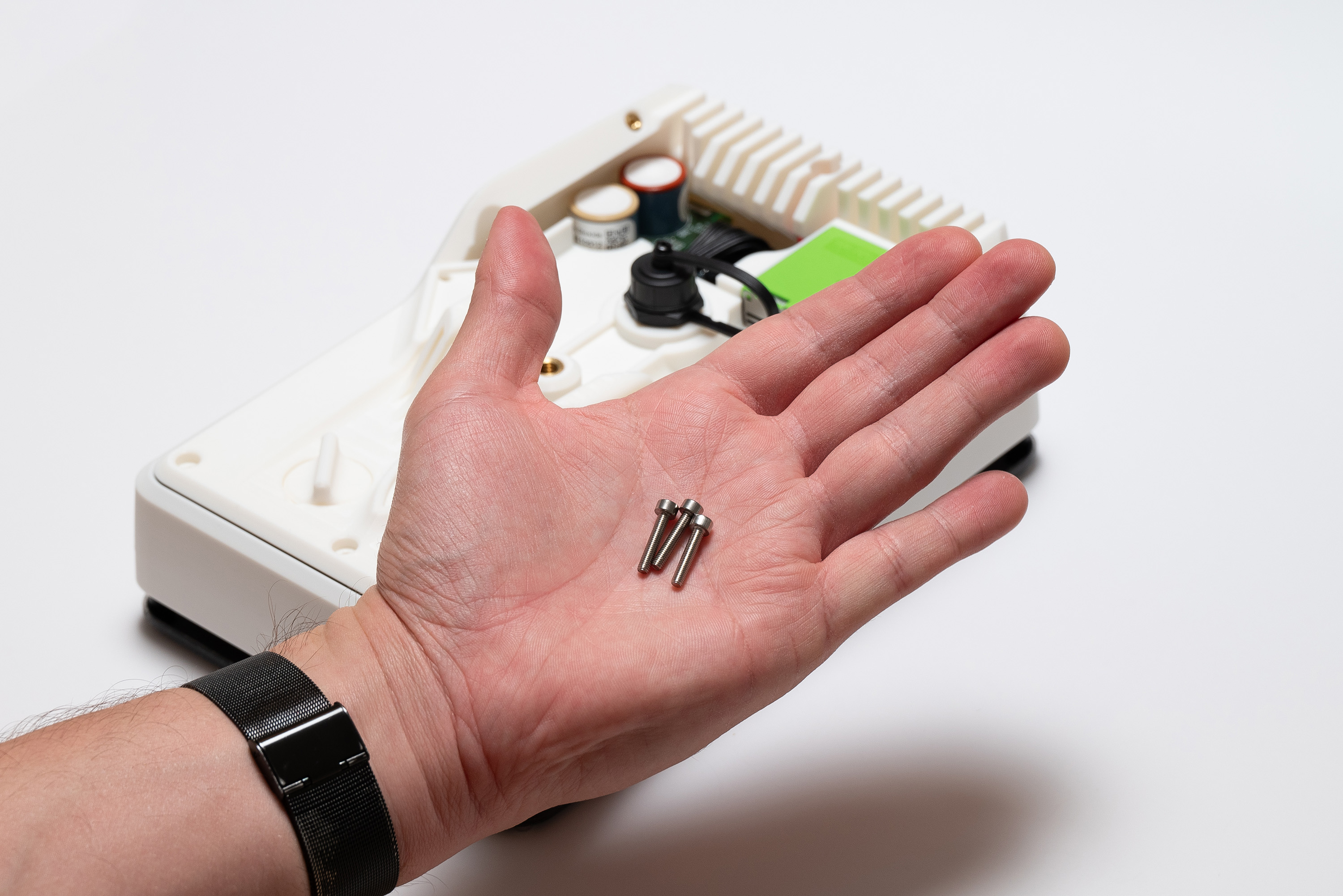
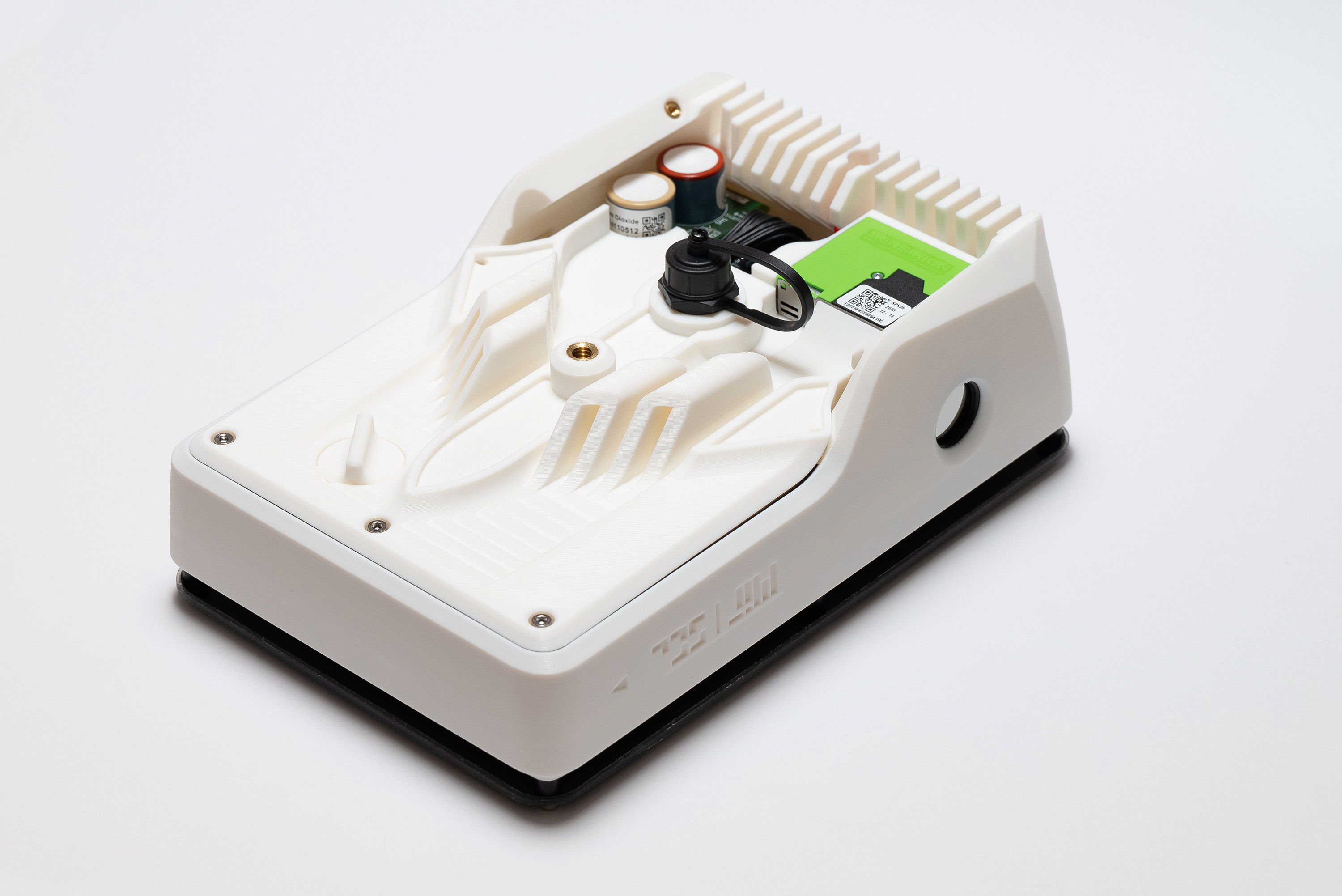
Place the last 4x M3x16 screws into the four bottom openings:
Fasten to hold it together with middle and top pieces:
Due to the angles it might be more dificult to fasten the screws than usual.
Instead of fixing one at once then proceding to the next, it is easier if each one is tightened a bit at a time.
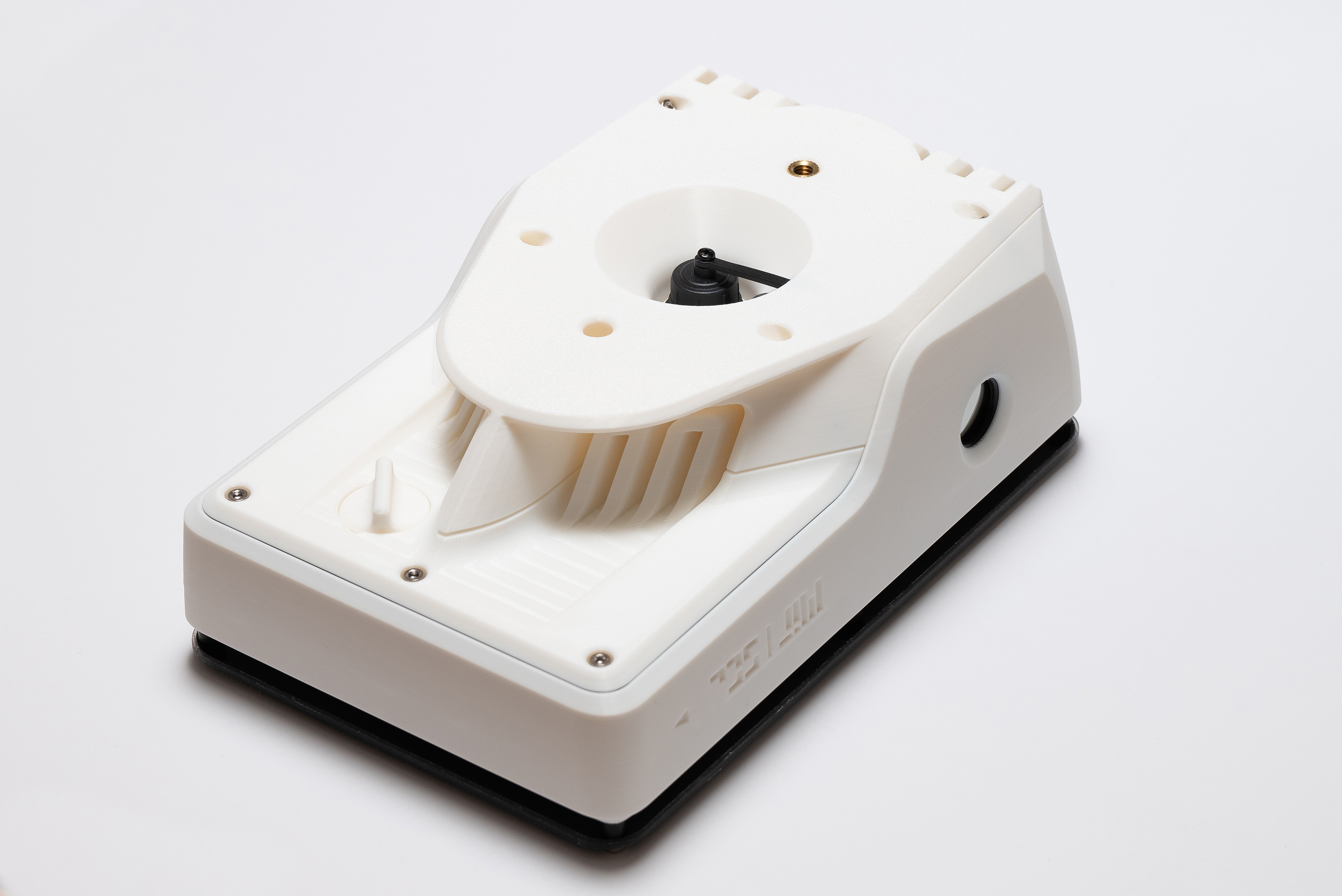
✅ Result
Make sure all seams are neatly aligned to avoid sealing issues.
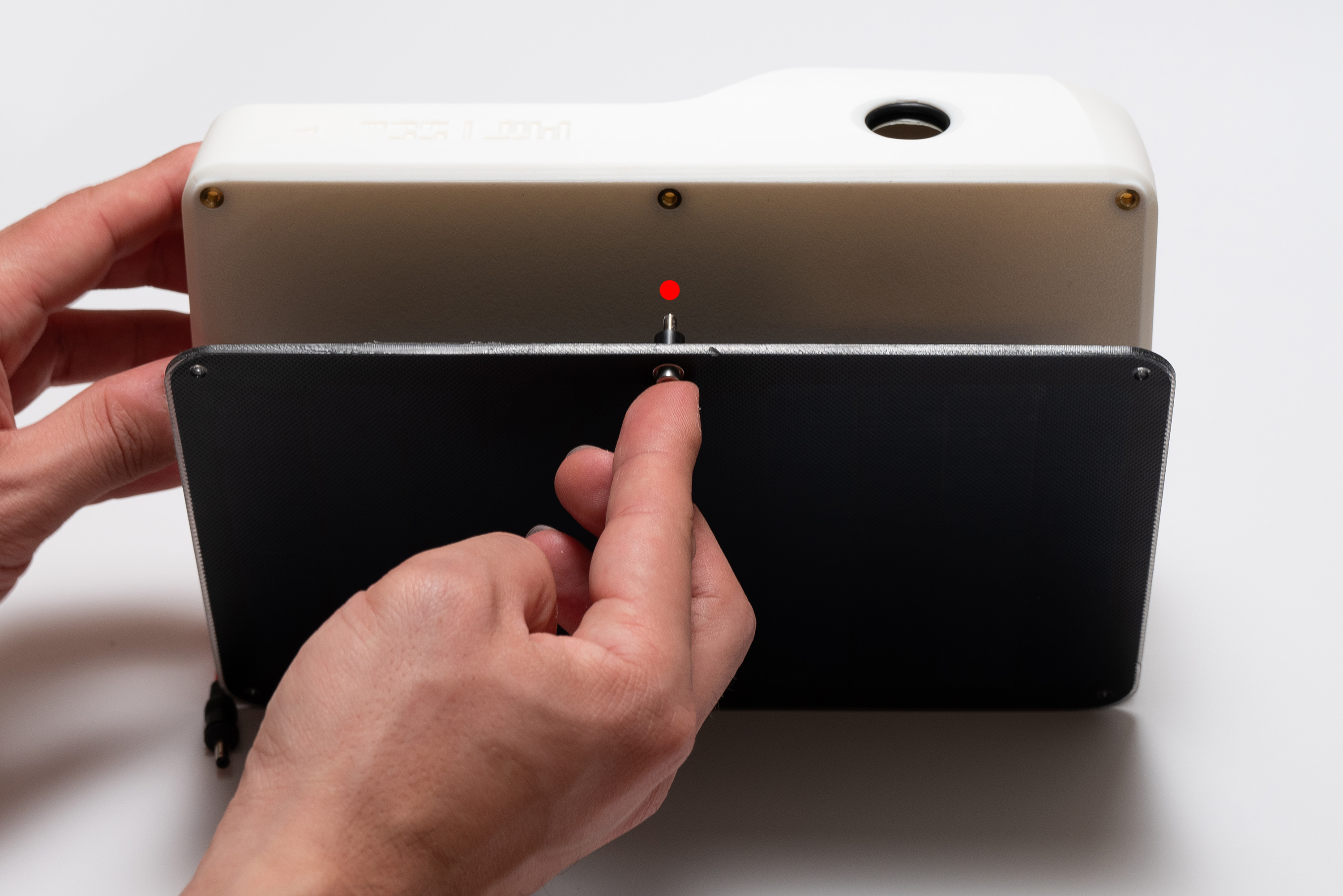
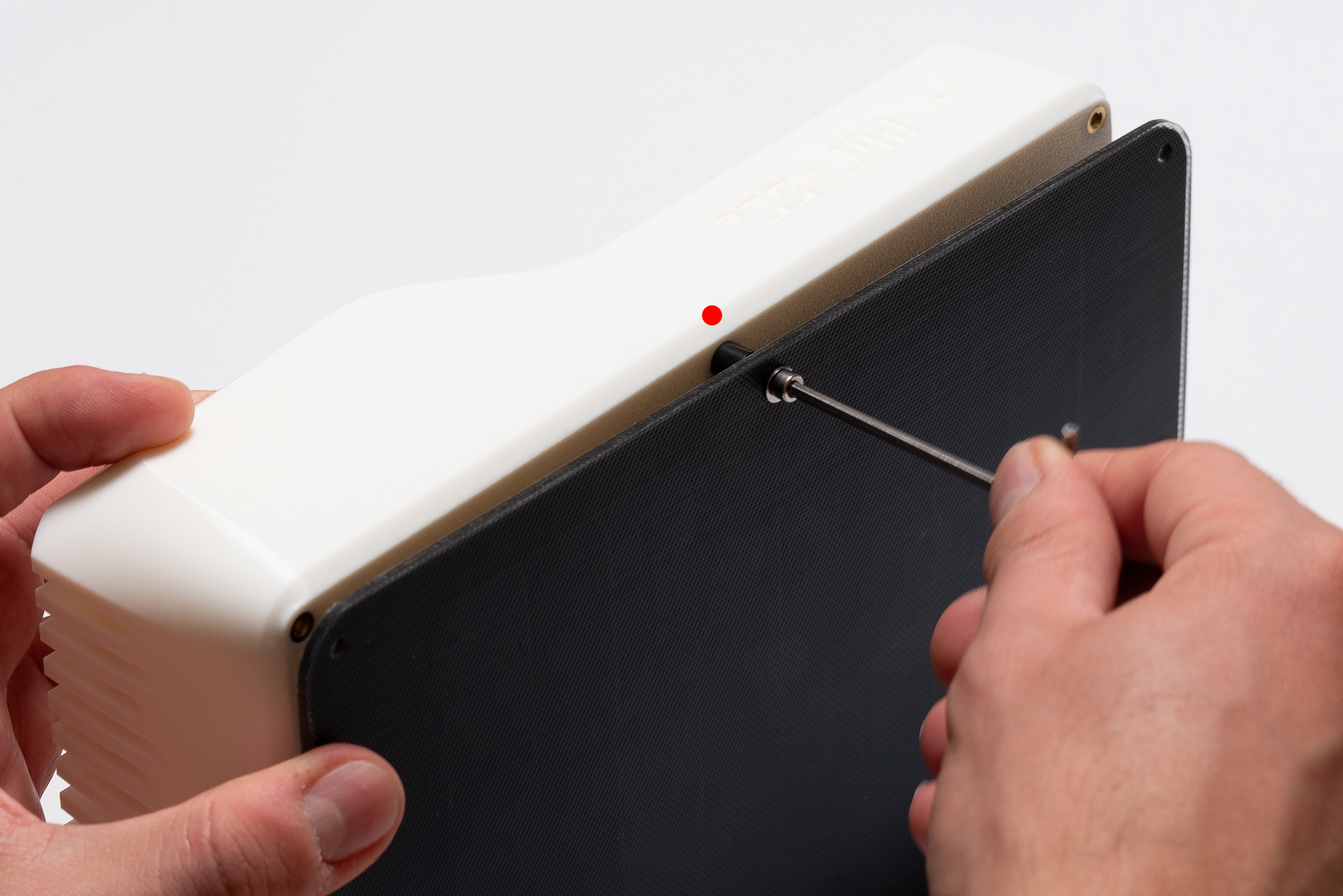
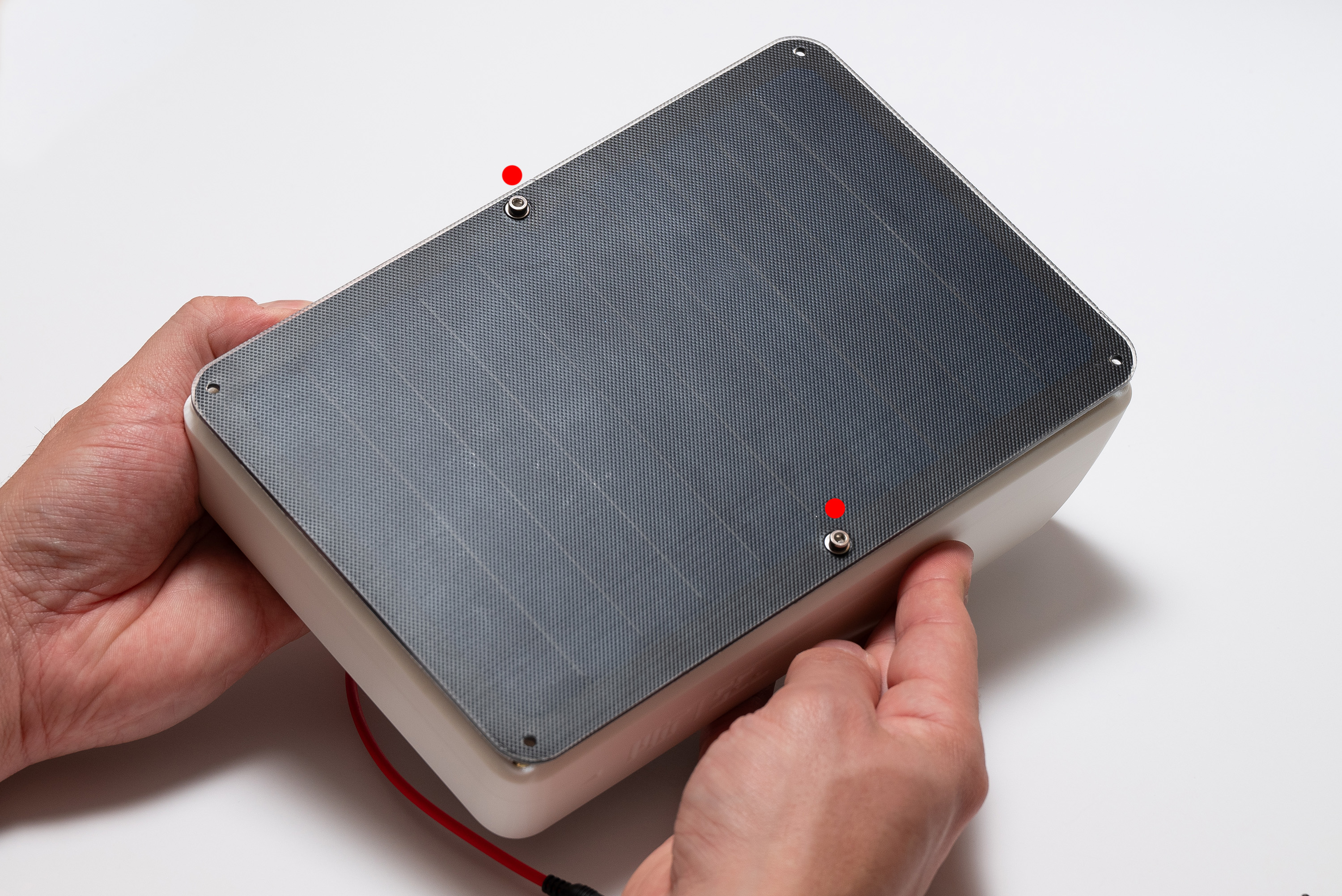
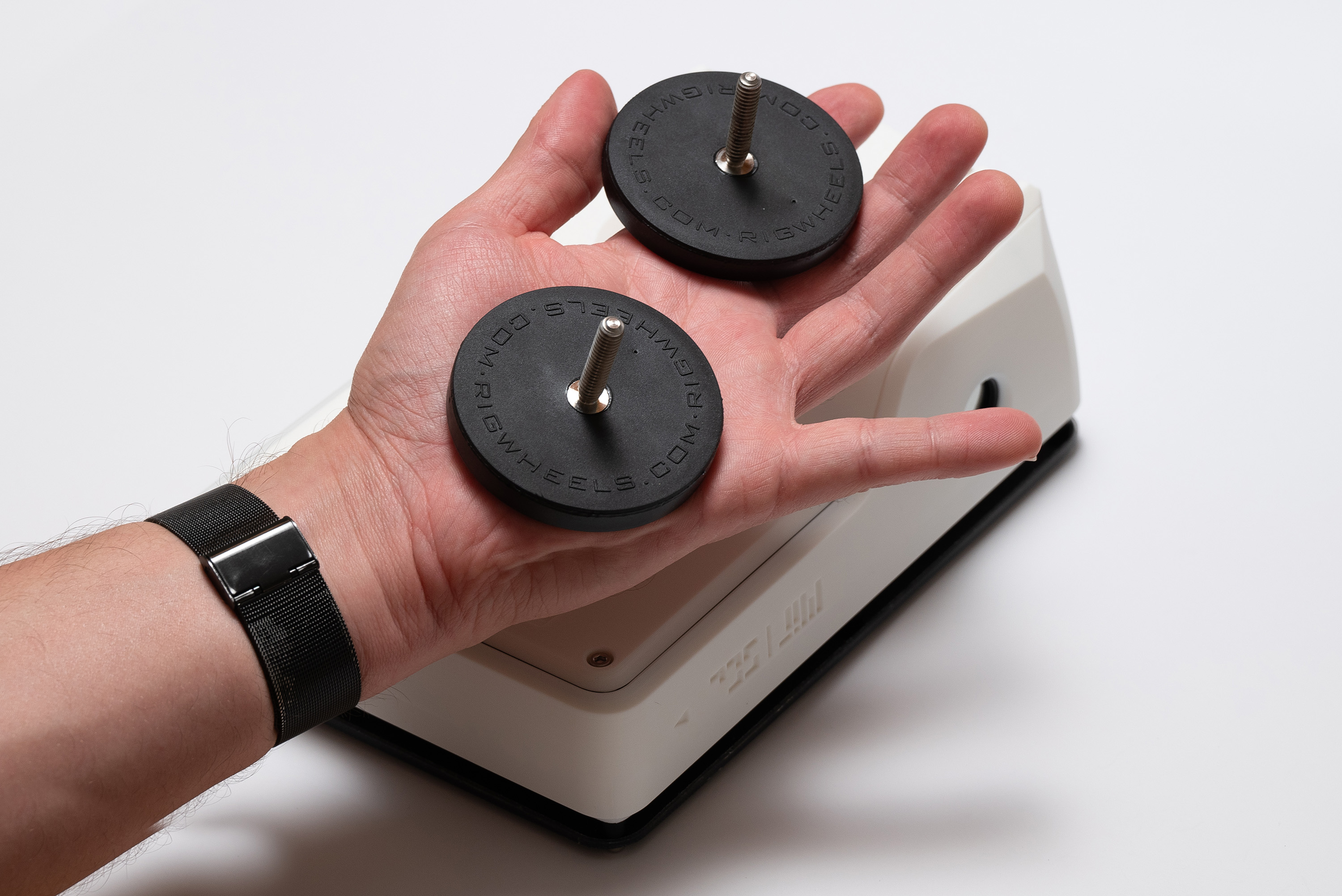
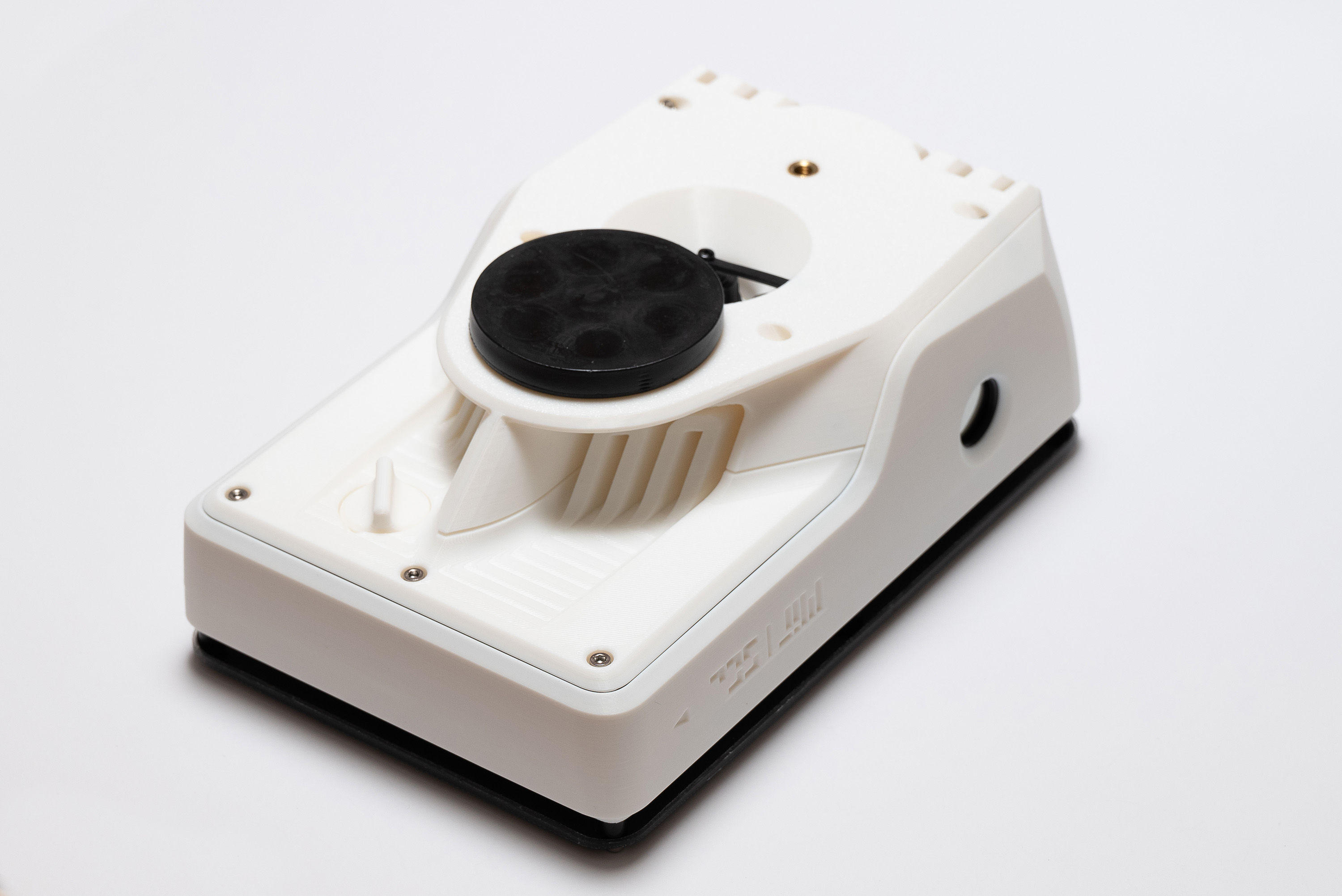
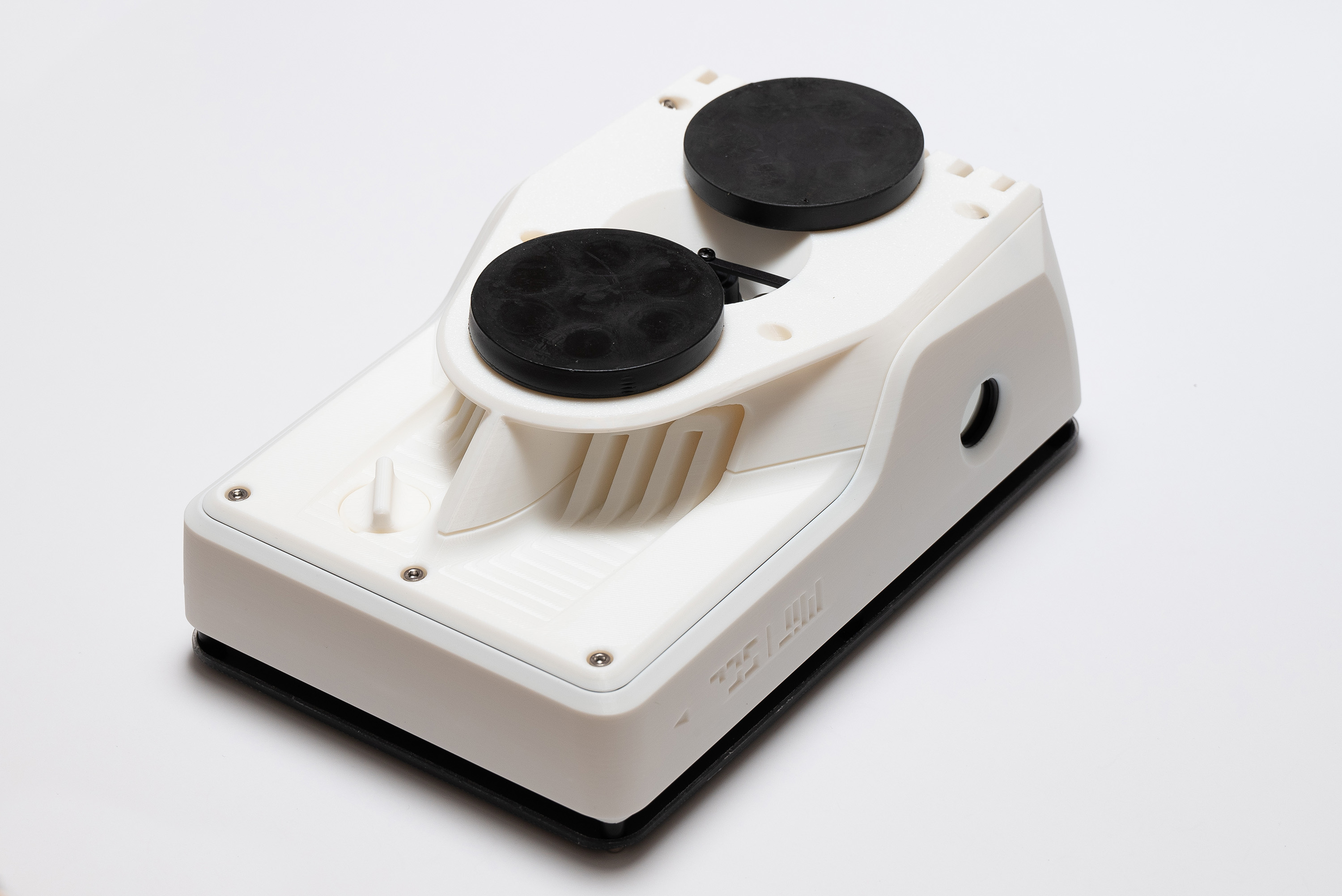
Step 19 – Magnets
Fasten both magnets into the botton piece, making sure it is well tightened:
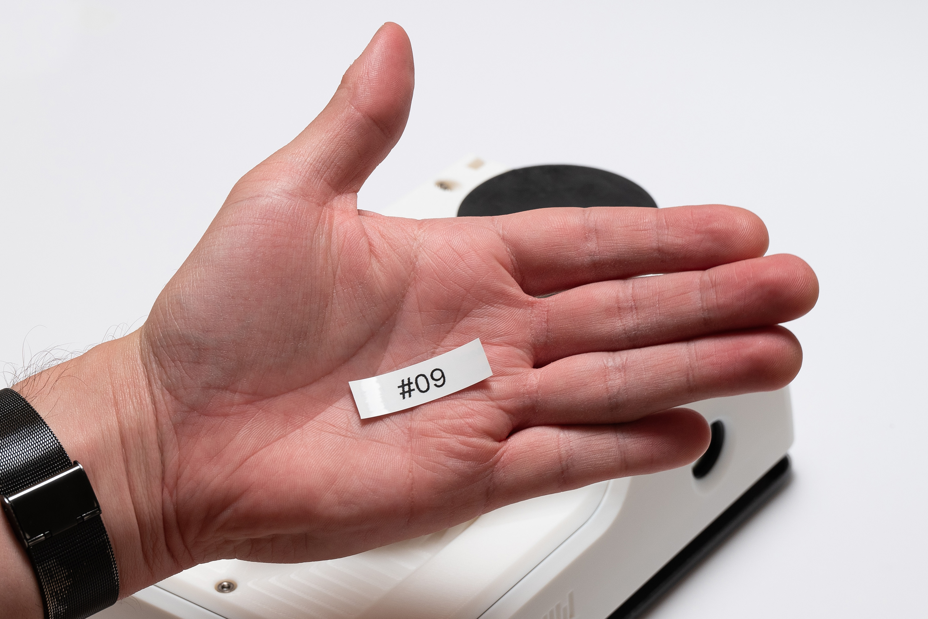
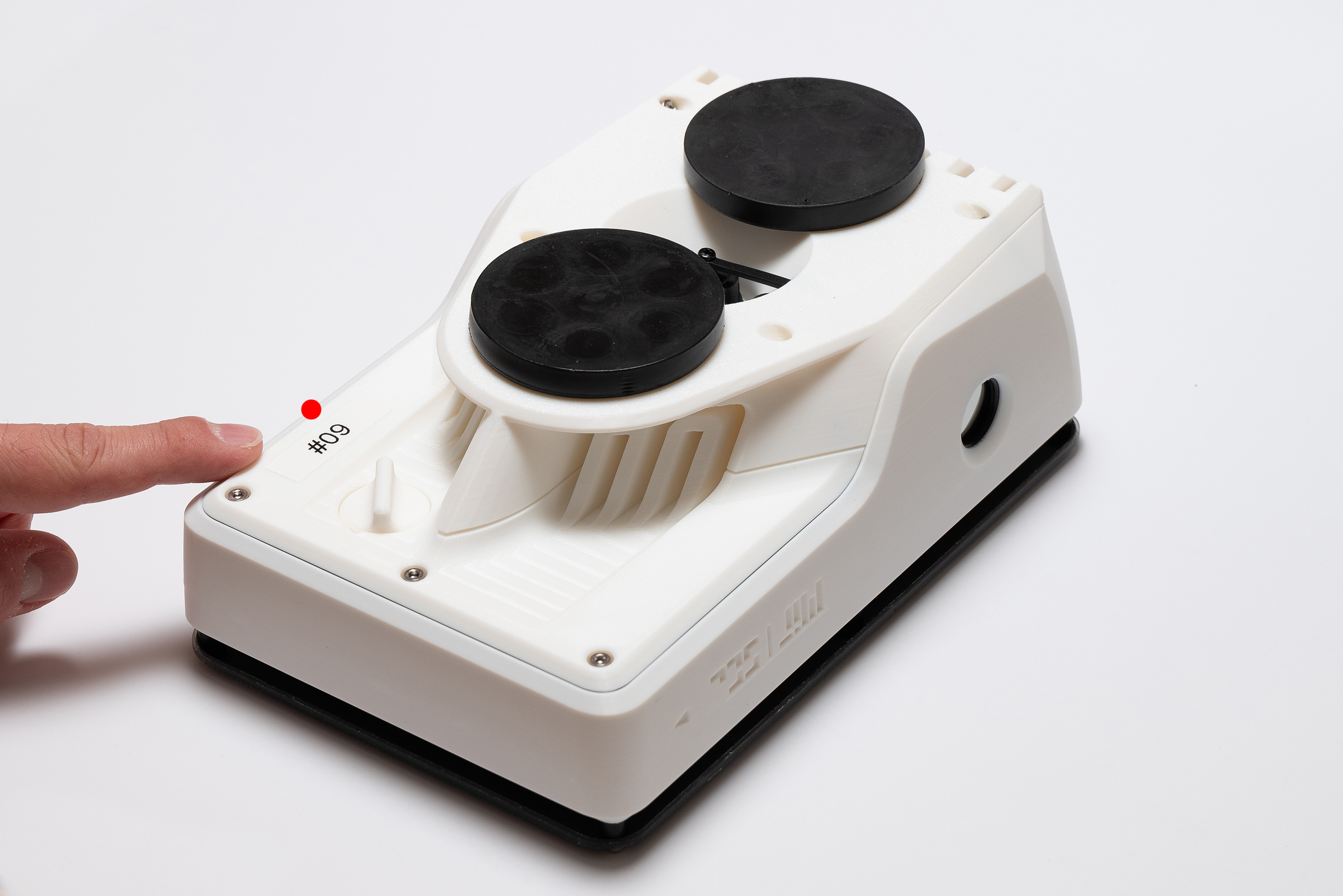
Step 20 – Identification
It is recommended to label each unit with a unique ID to avoid data identification issues:
You made it!