🧩 Assembly
It is highly recommended that you read this entire assembly manual to familiarize yourself before starting!
Overview
The assembly process consists of 14 easy steps, which should take up to 60 minutes per device.
The device was designed for not needing wire soldering, glueing or any other complex operation.
You will be installing brass inserts into plastic, placing parts together, connecting cables and fastening screws.
Safety
- Be aware of the soldering iron tip and hot parts to avoid burning yourself and the 3d printed parts.
- The metal inserts will keep hot for a while after inserting, especially the bigger 1/4" ones.
Step 1 – Setup and Preparation
- Make sure there is enough space and lighting;
- Have all parts and components accessible on bench, placing the smallest ones on "buckets" to avoid losing them;
- Leave the center of the bench for where the actual work is going to be, and the perimeter for tools and other parts;
- Keep dangerous tools such as the soldering station away from where you could accidentaly hit it by mistake.
- Print all 3D printed parts - you can consult the materials for printer settings and files.
Meanwhile, you can always consult the overview reference, bill of materials and suggested tools throughout the process.
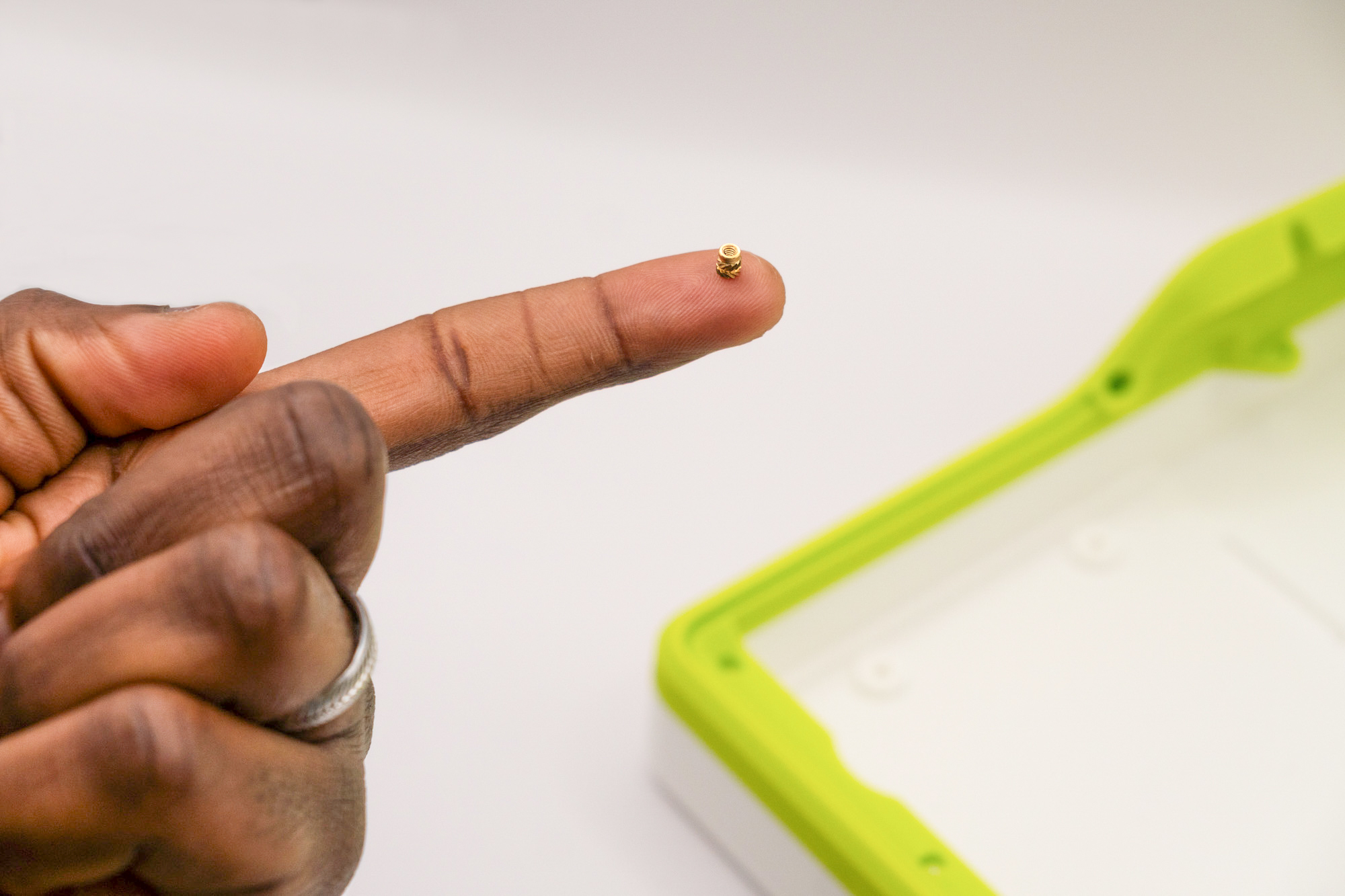
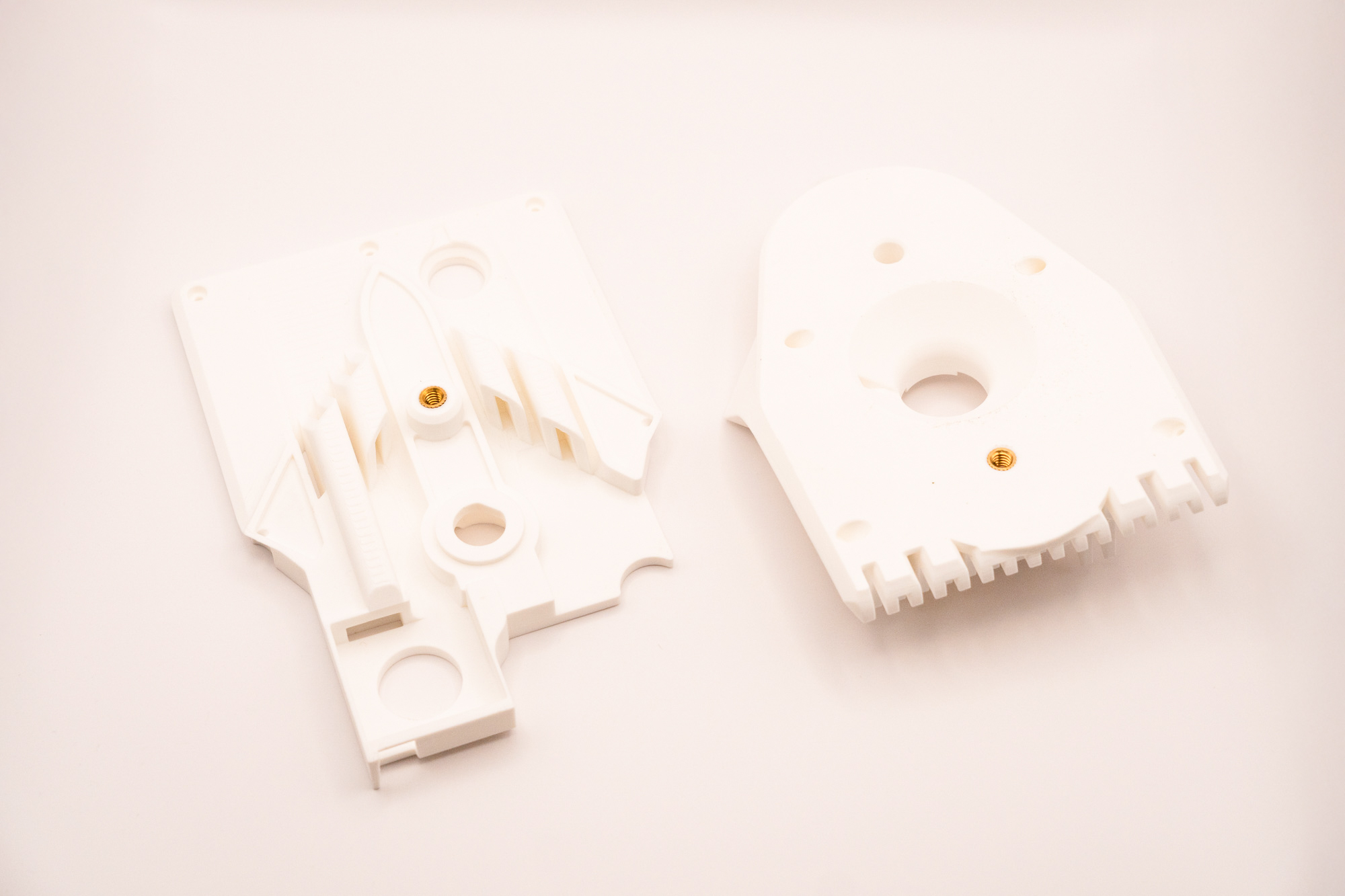
Step 2 – M2 Inserts
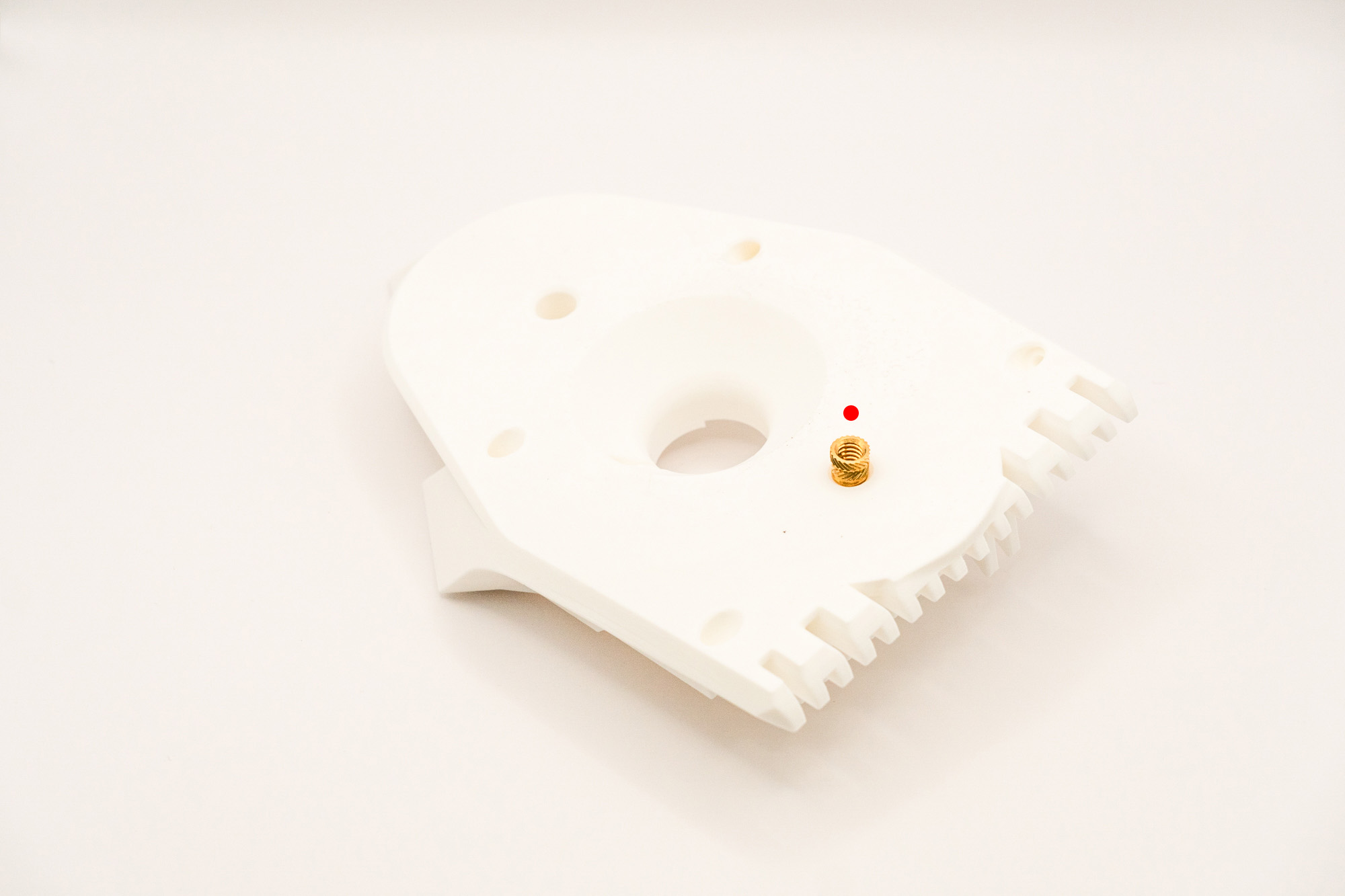
- It is easy to misplace the inserts, pay attention to the indicated spots on the images.
- The larger holes are meant for the 1/4" inserts, the medium for M3 and smaller for M2 - the documentation will indicate where to put each specific insert size.
- After the inserts are melted into the plastic they cannot be easily removed without damaging the 3d printed part.
- If in doubt, think twice and check the instructions!
Start by picking-up all the thirteen M2 inserts
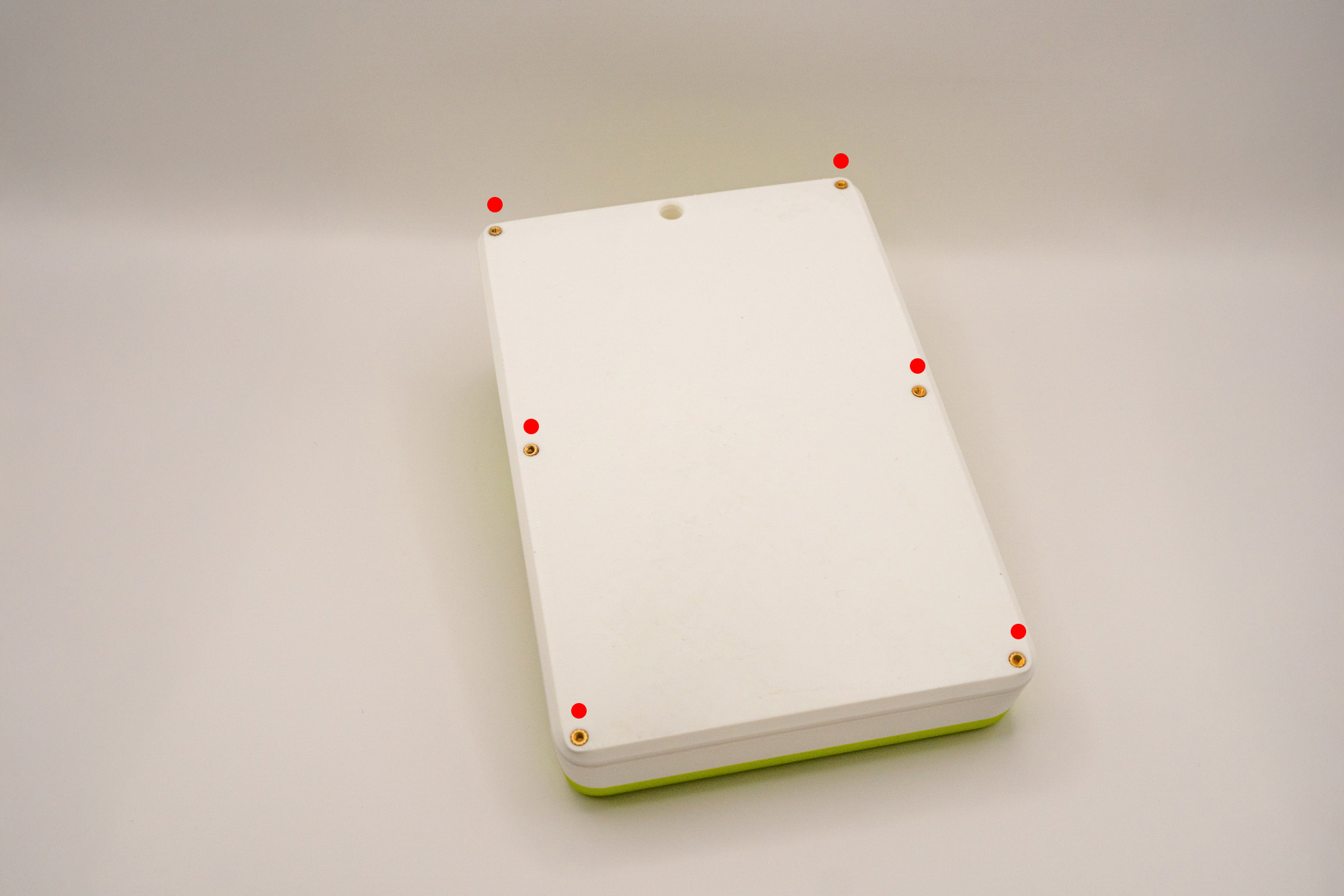
Of which, place eight M2 inserts on top:
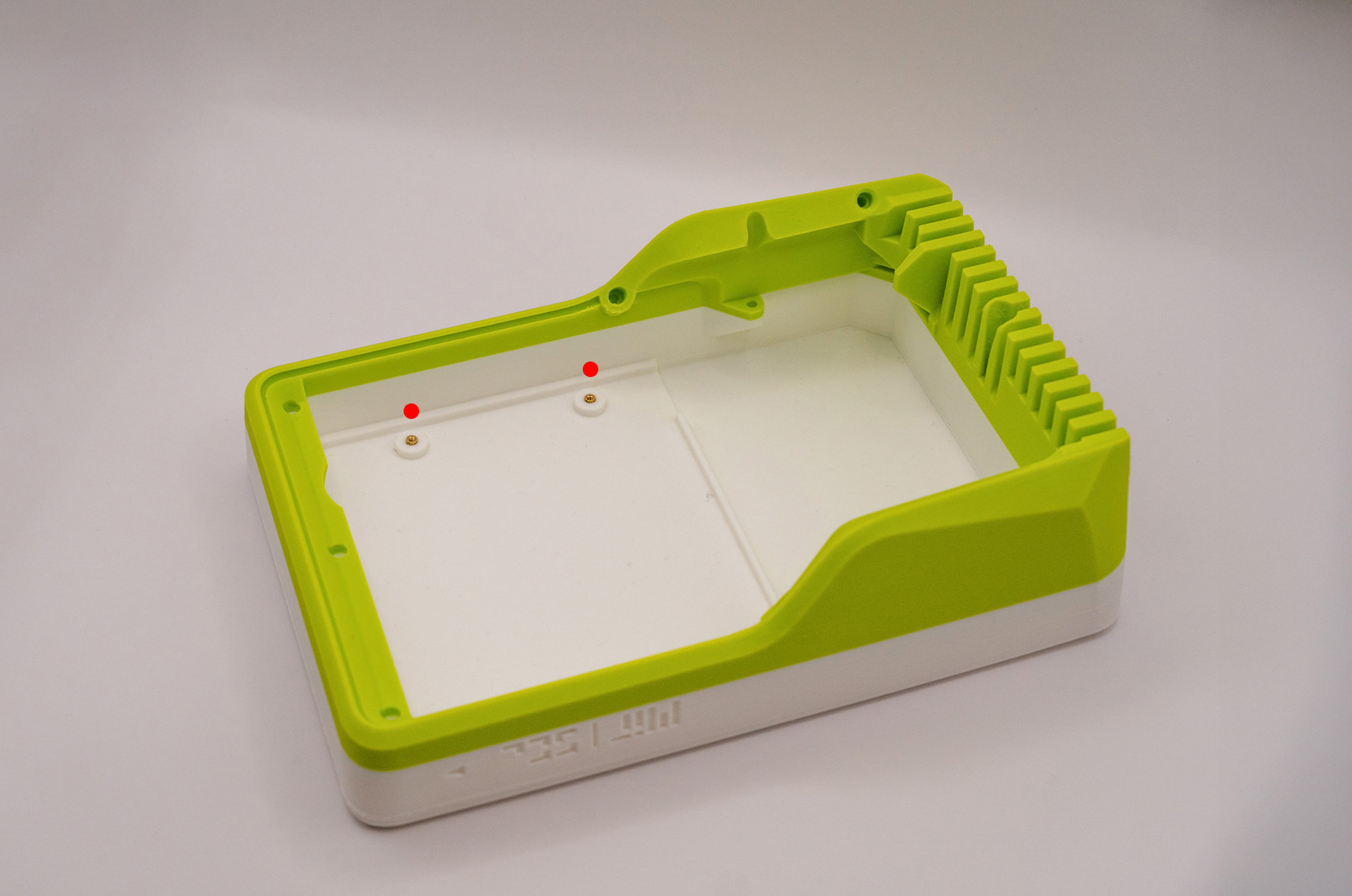
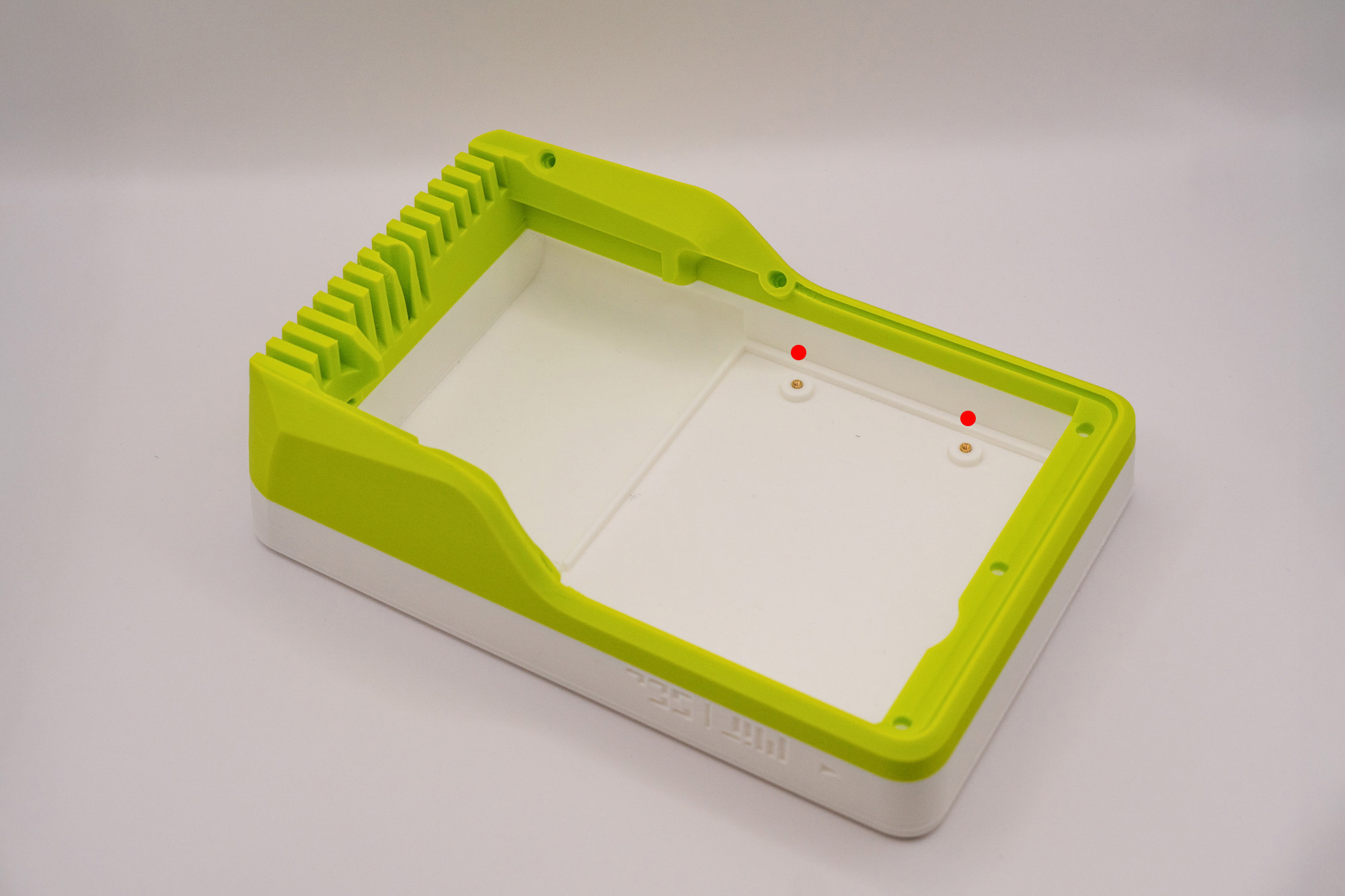
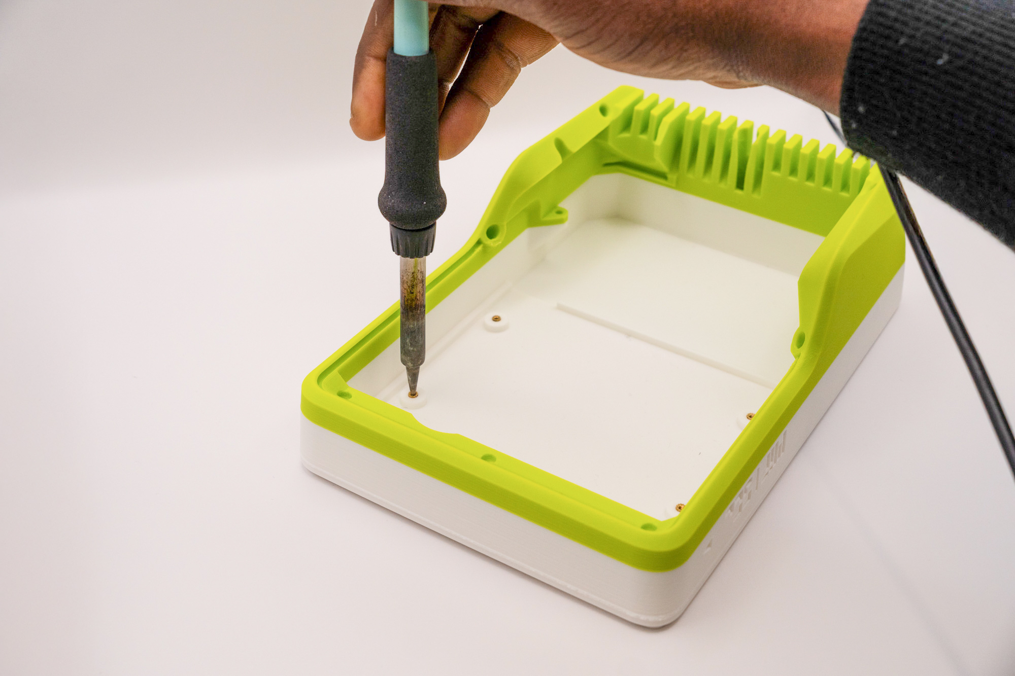
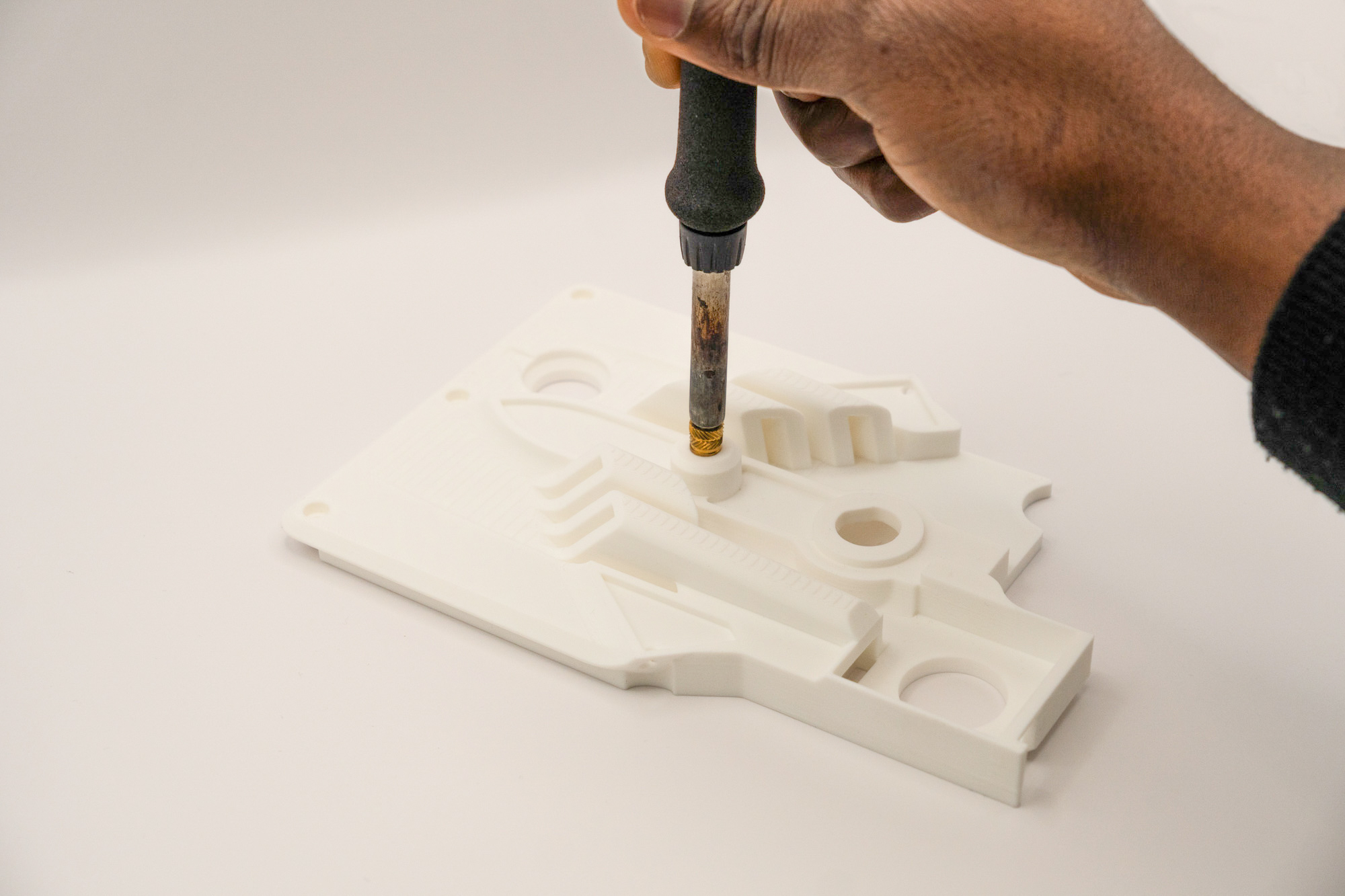
Set the soldering iron to 300ºC, wait for it to reach the temperature, then slowly press the soldering tip perpendicularly (avoid twisting) to the inserts until all them are flush with the printed surfaces:
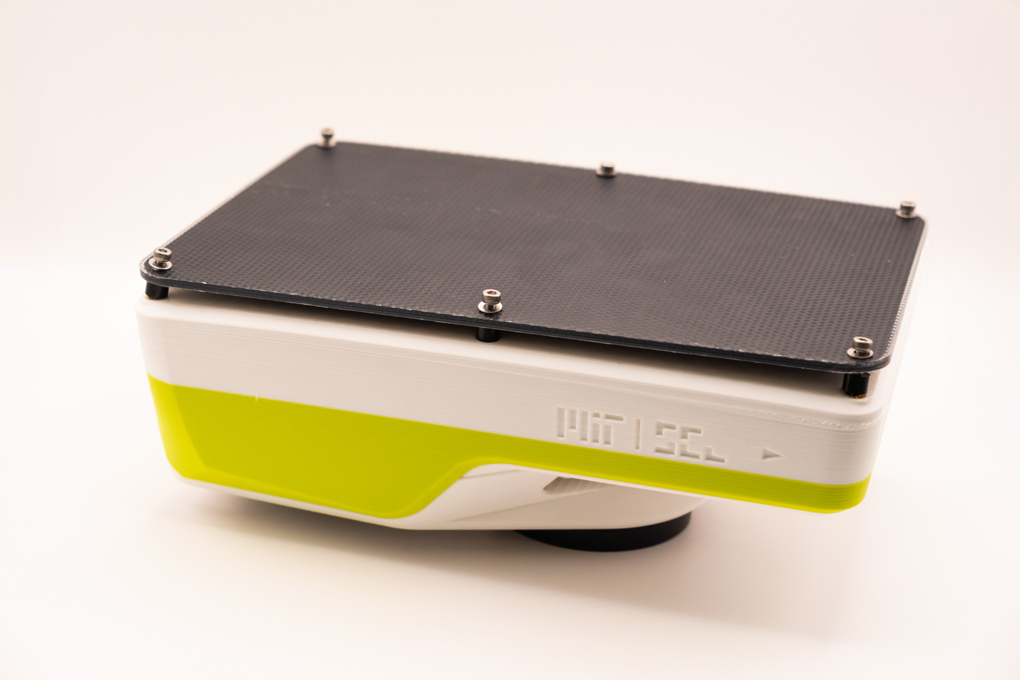
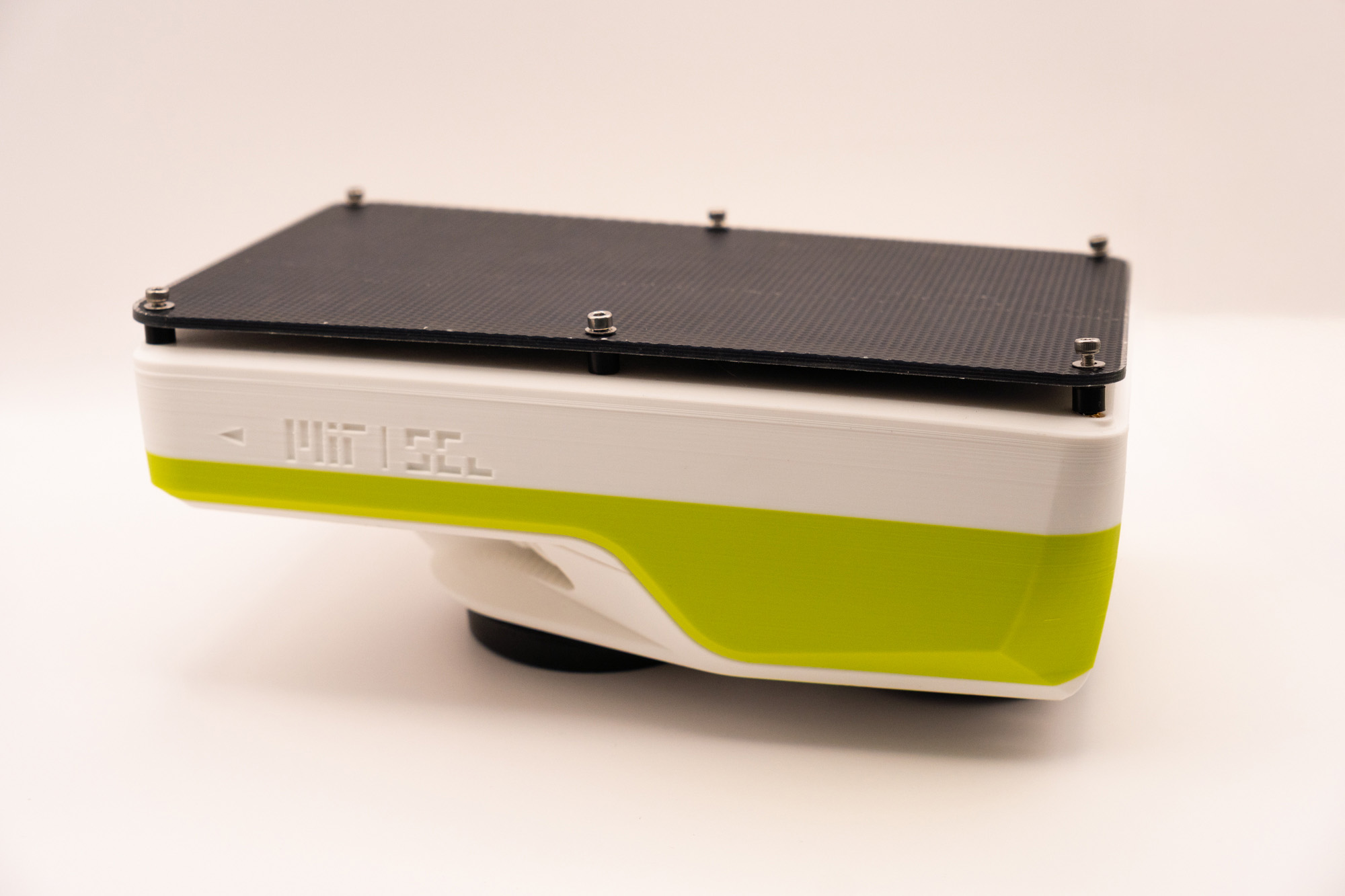
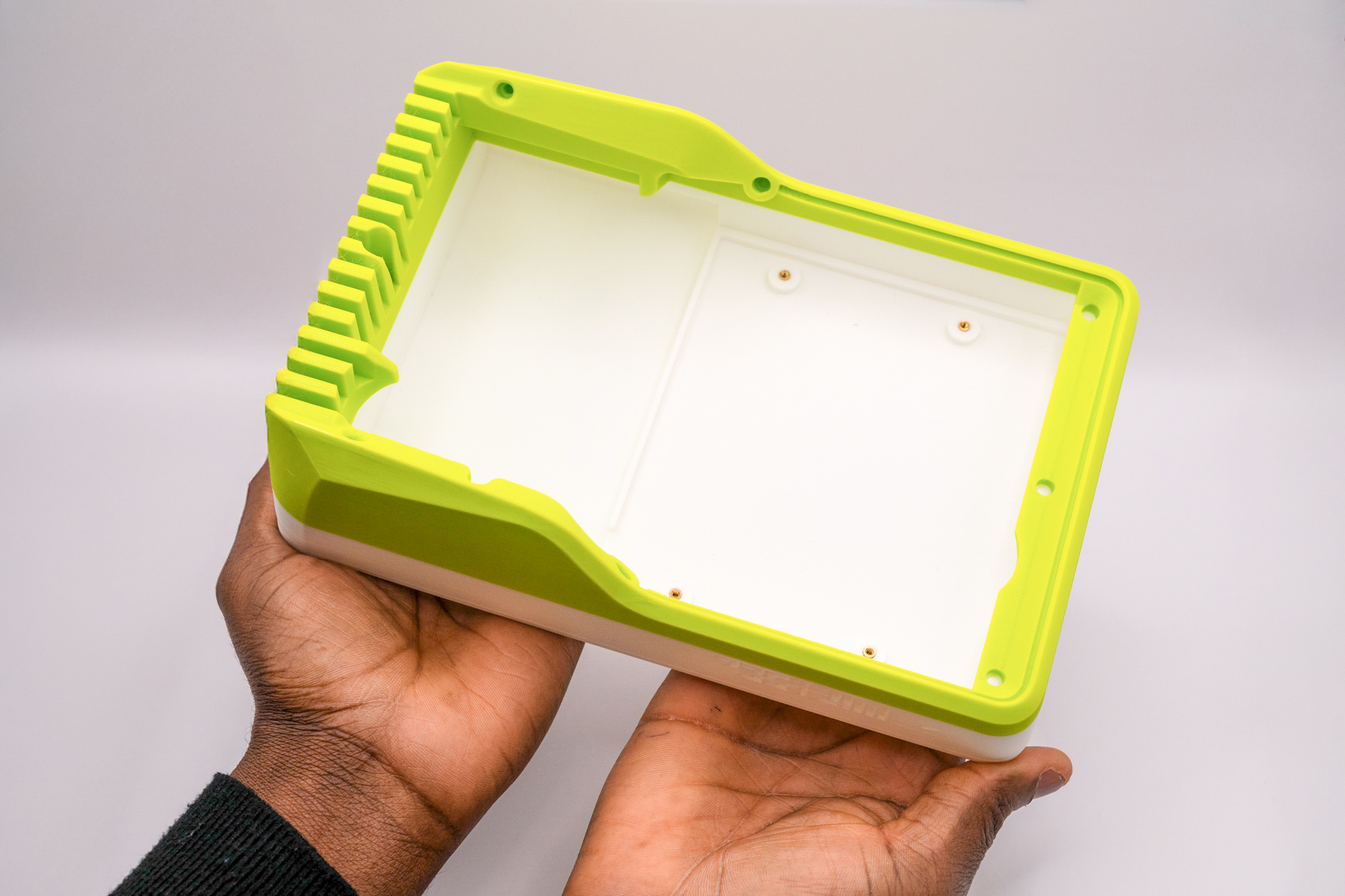
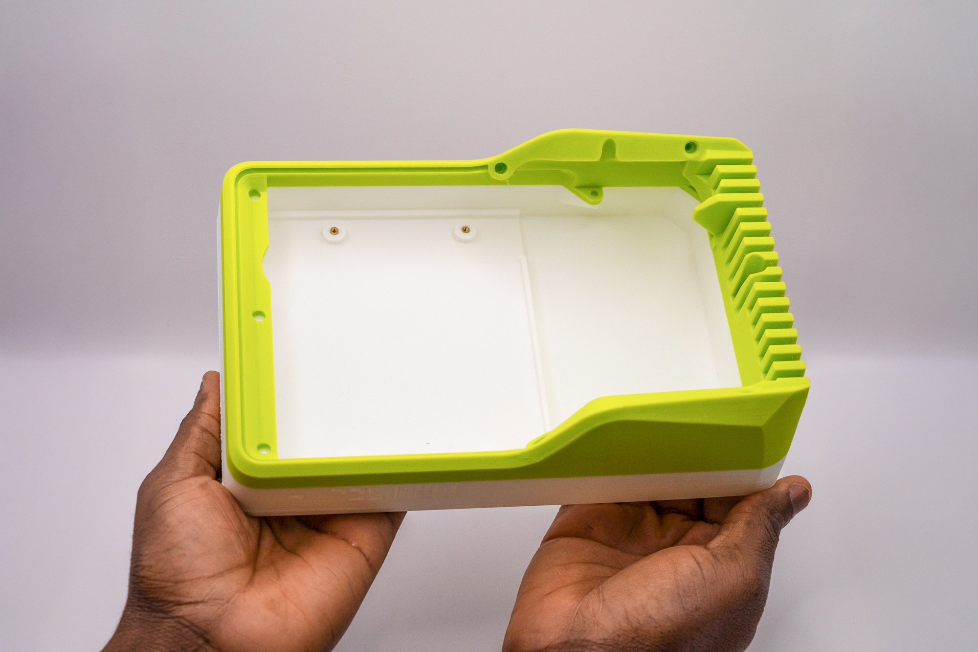
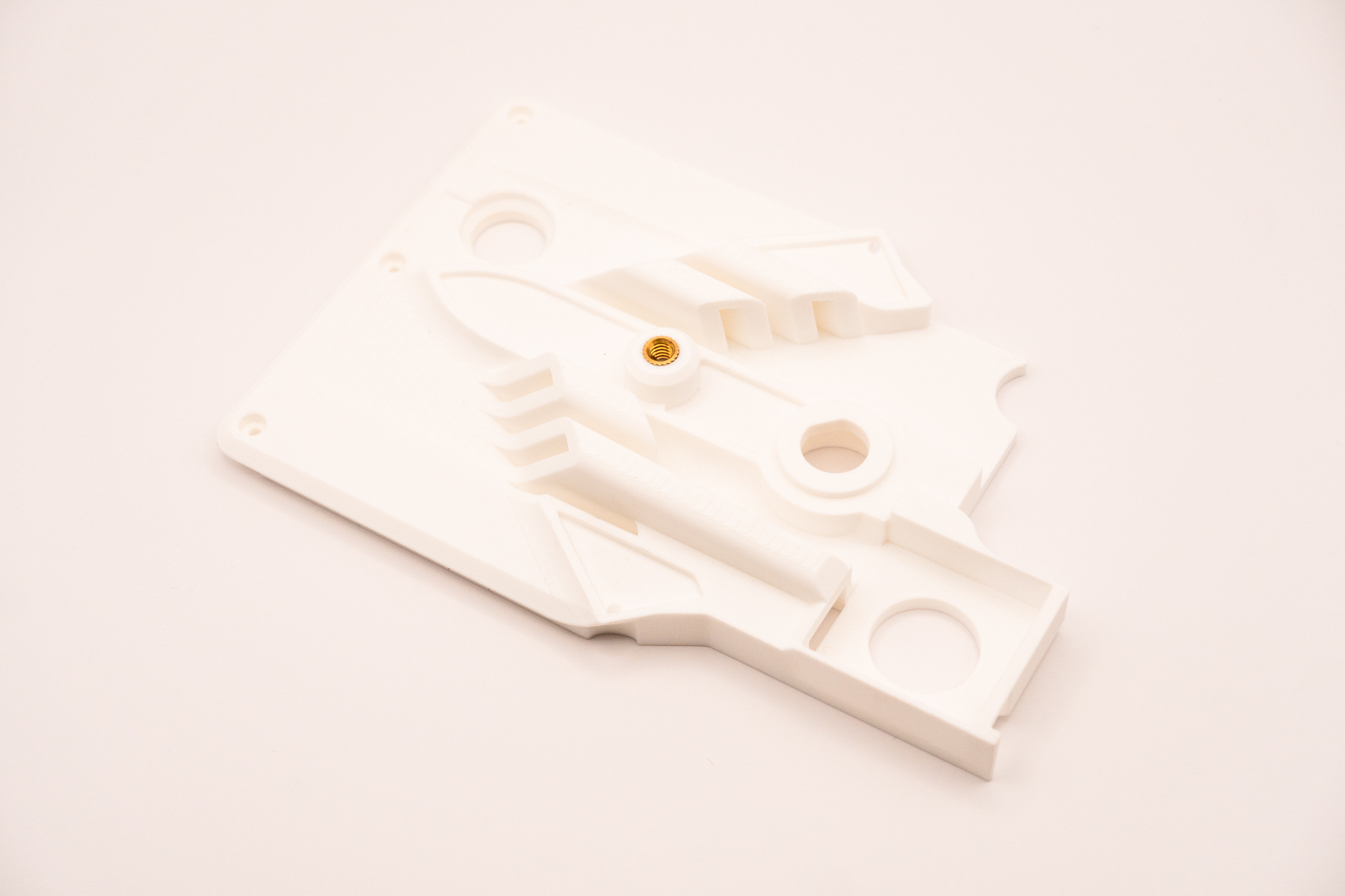
In the end, this should be the result:
✅ top
Step 3 – M3 Inserts
Pick-up thirteen M3 inserts, turn the top piece around, then place six M3 inserts on it:
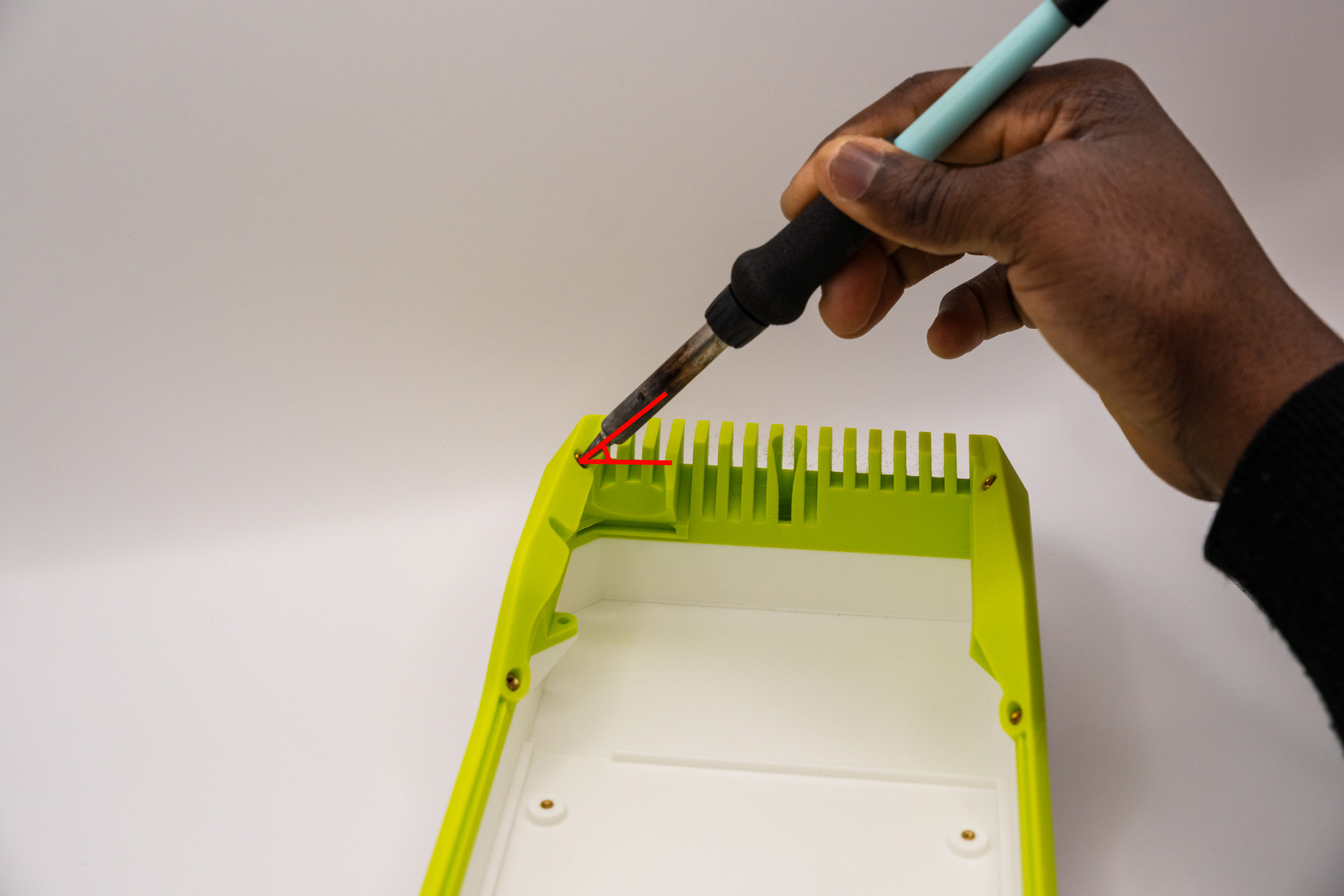
Then, install the six inserts with the soldering iron, turn the top piece back and place the remaining eight M3 inserts on the other side:
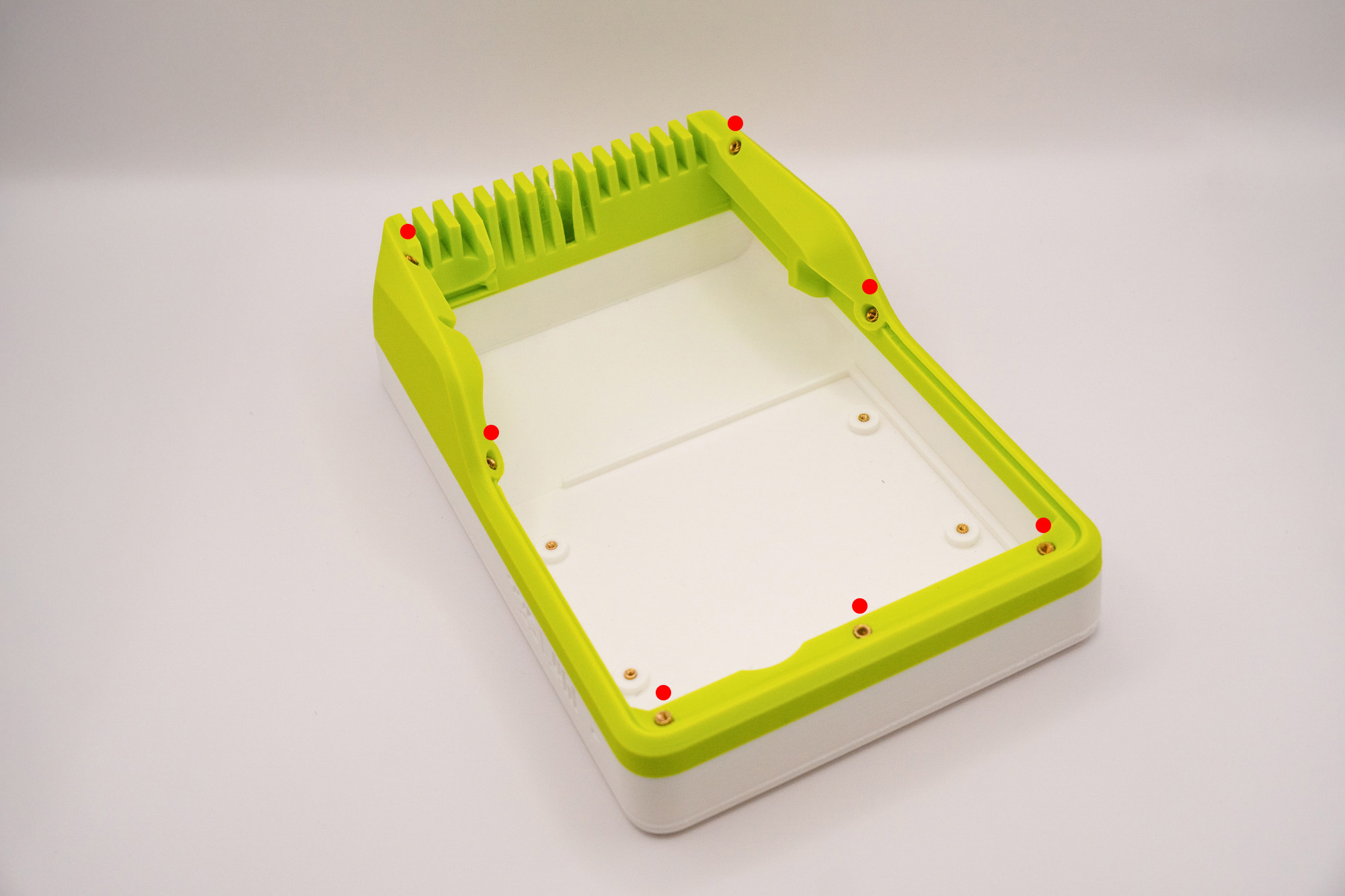
Pay attention to the appropriate angle, respecting the holes' directions and the surface alignment:
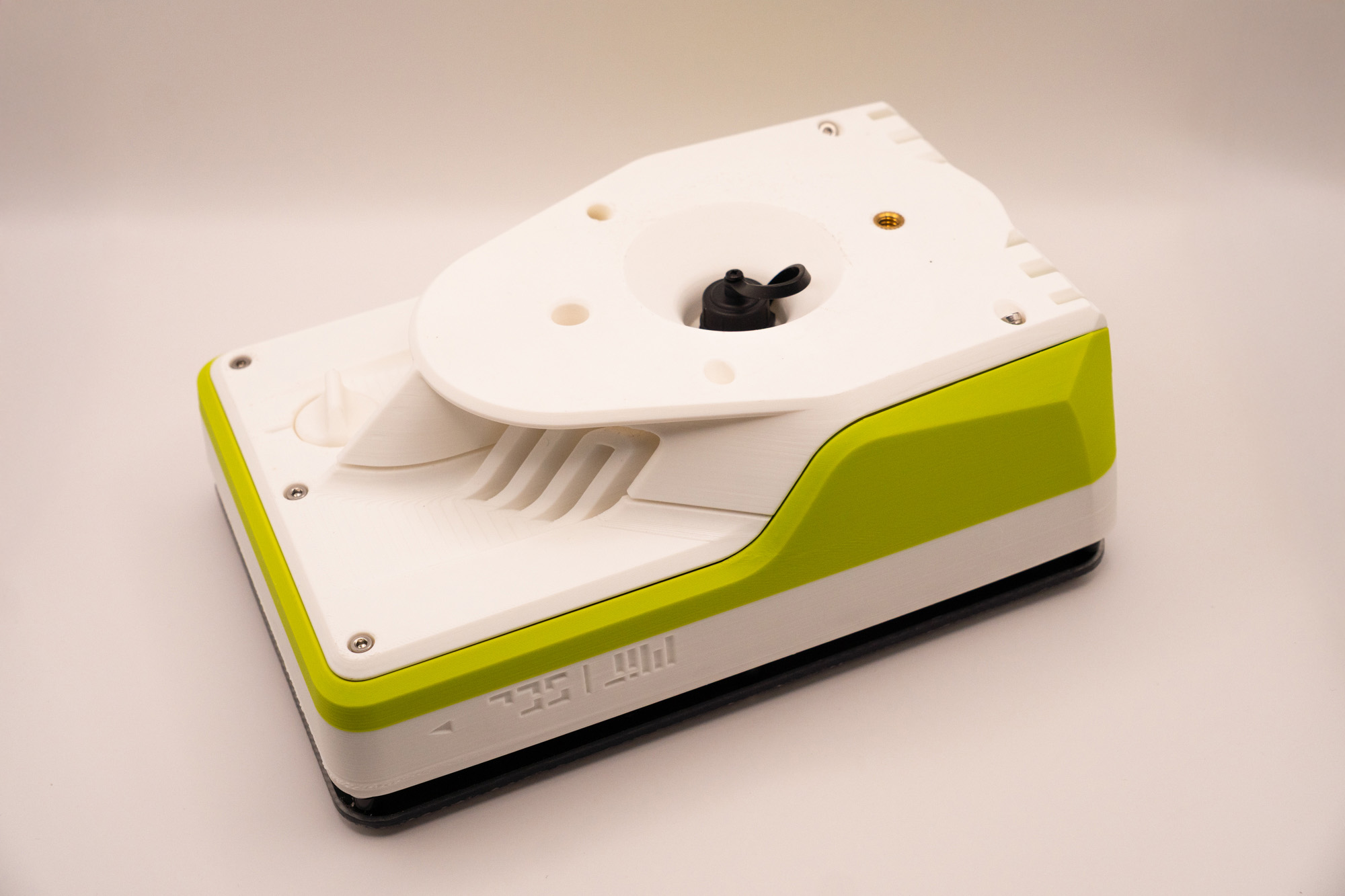
Step 4 – 1/4" Inserts
Place a ¼" insert on the designated spot on middle piece:
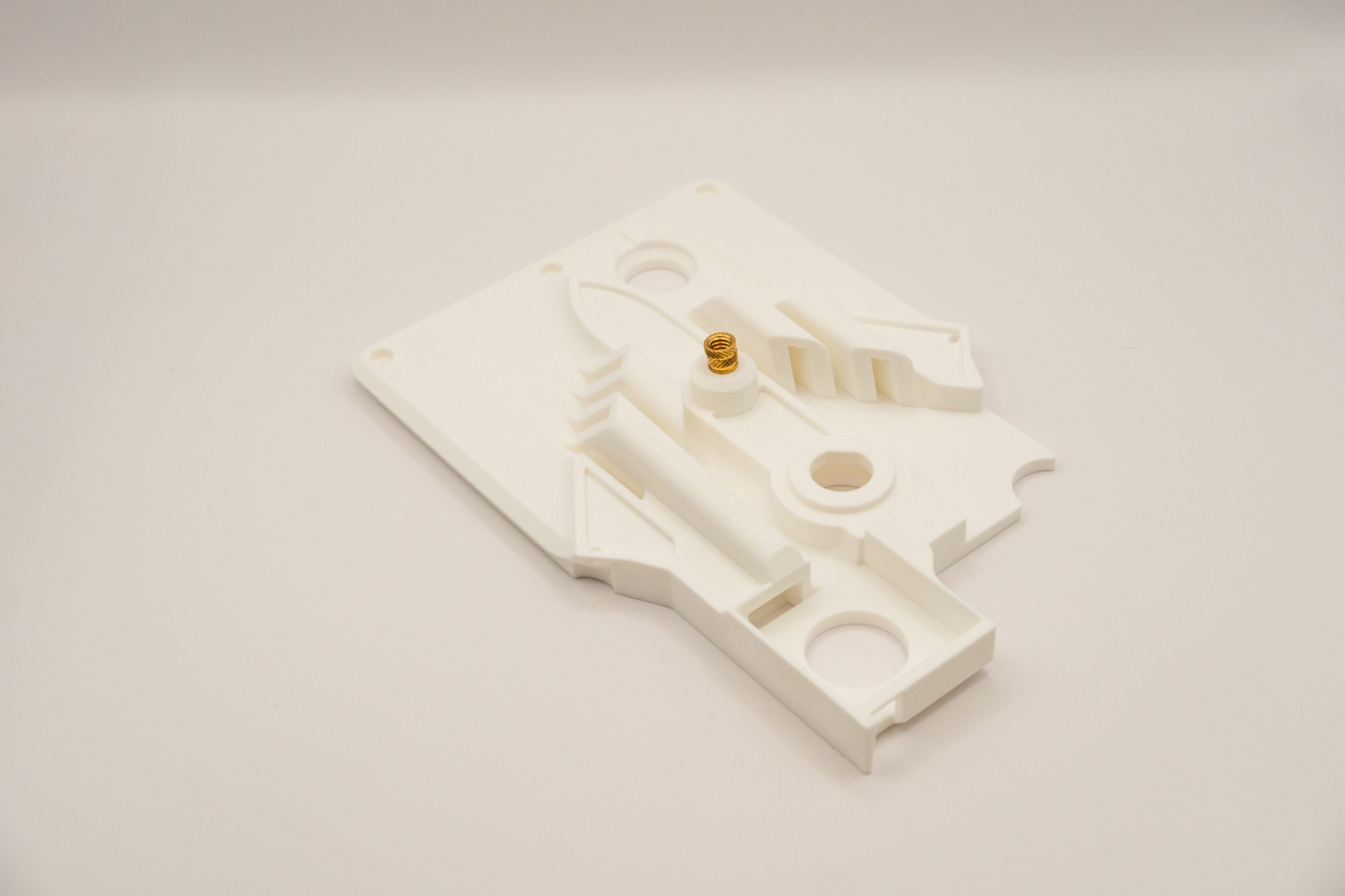
Be careful, these bigger inserts take longer to heat and to cool down.
Then, place the other ¼" insert on the rear spot of the bottom piece:
Be careful to not place the insert in the wrong spot
✅ Result
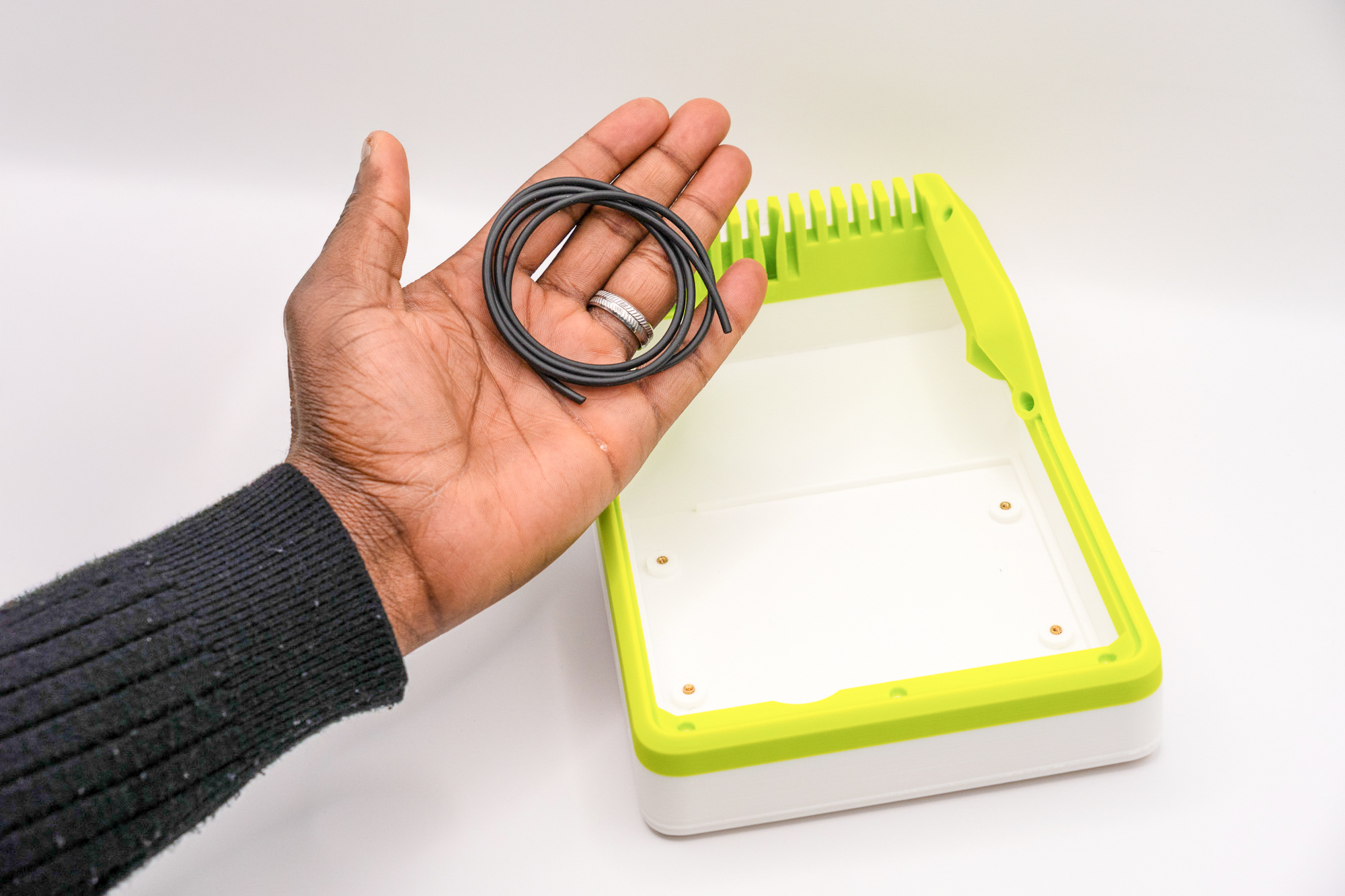
Step 5 – O-Ring Cord
Pick the O-ring cord and unroll it:
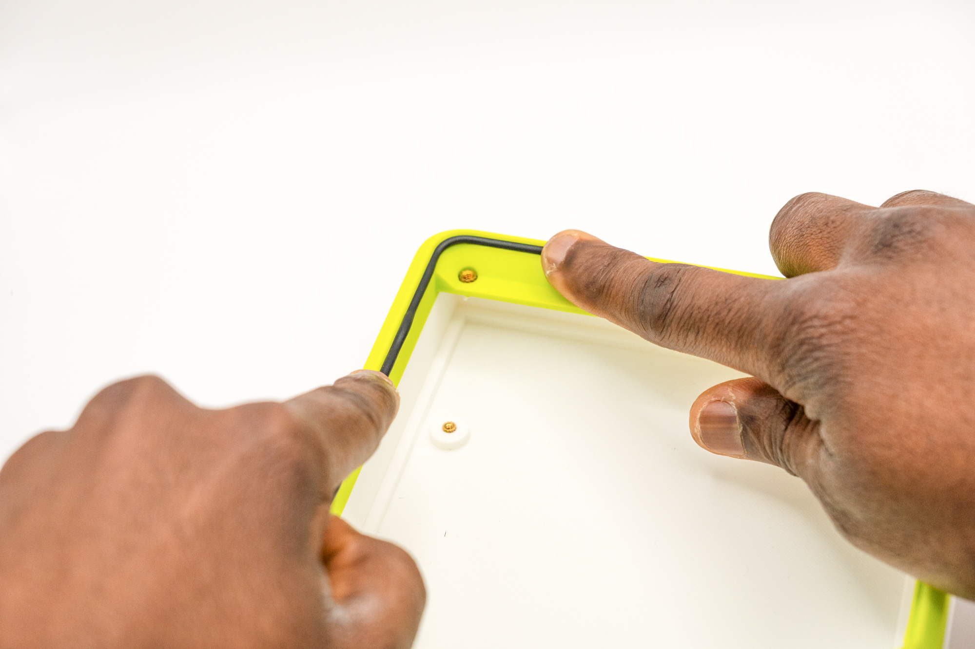
Align the tip of the cord to the recess on the top piece, then gently press it perpendicularly to fit inside:
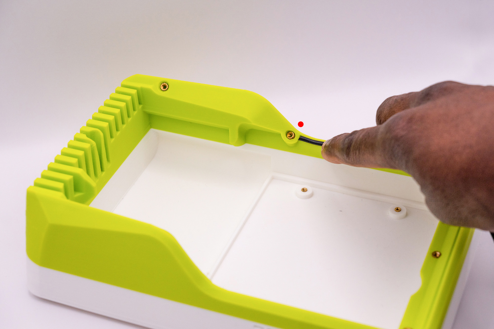
Without stretching, keep pressing until reaching the other extremity of the recess:
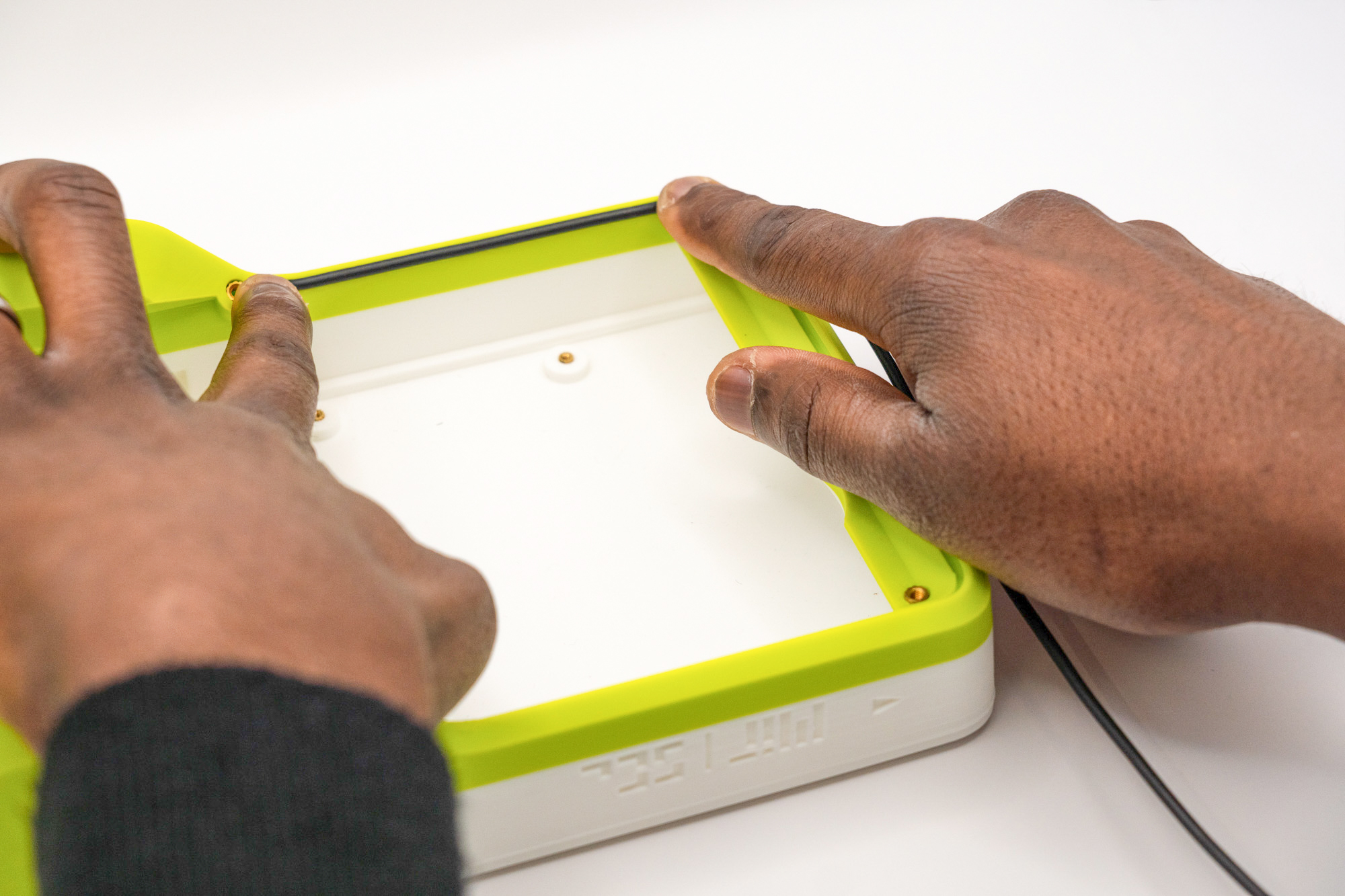
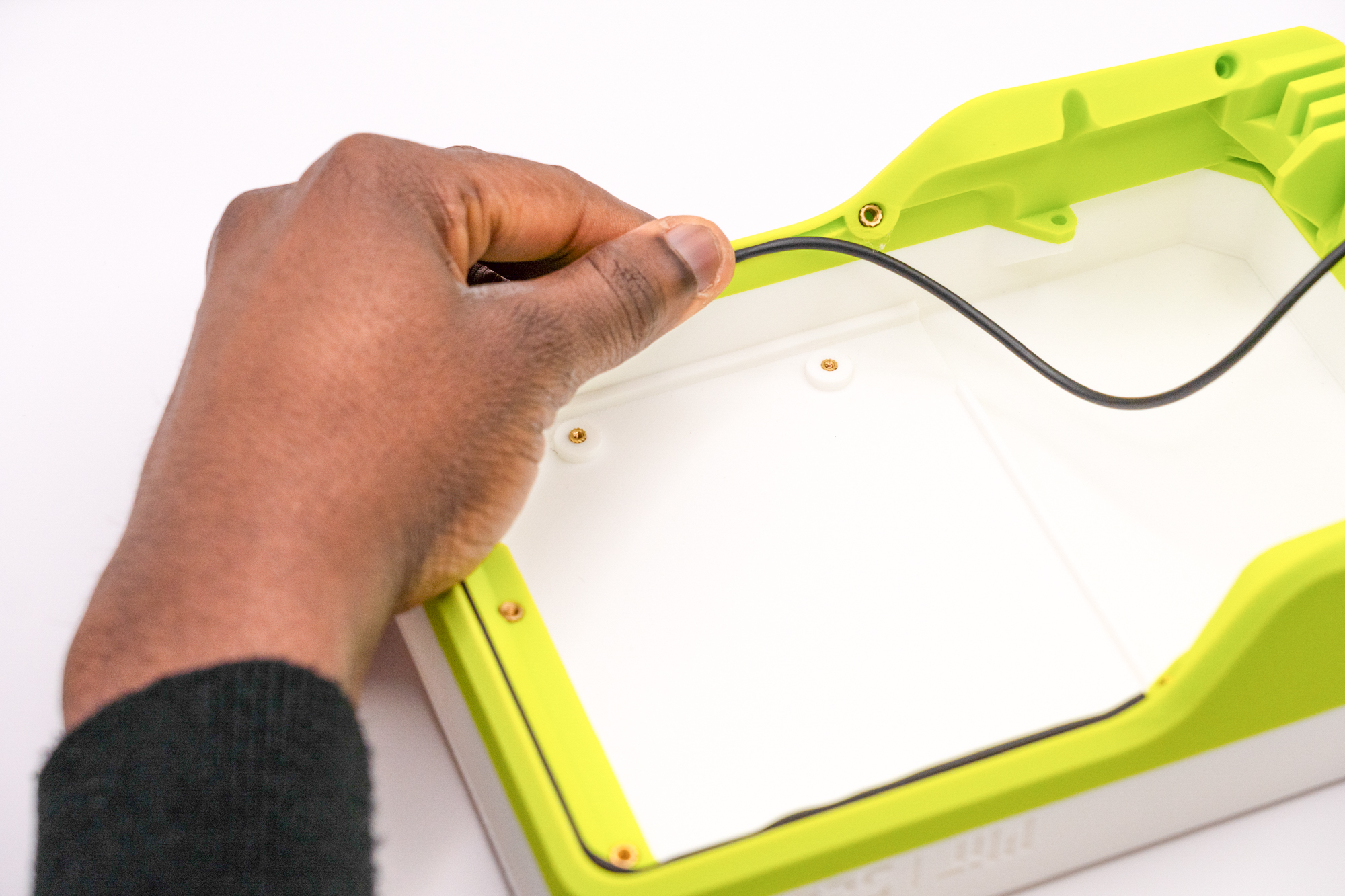
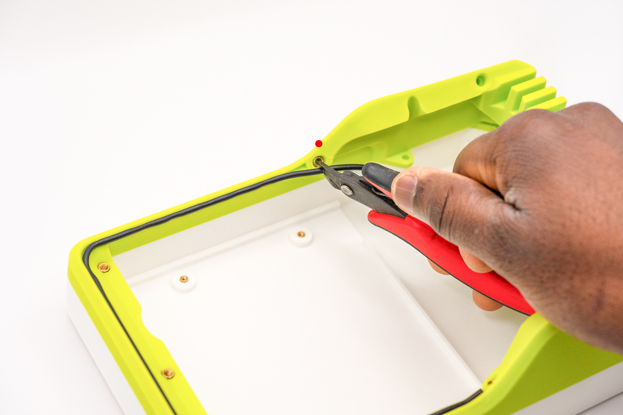
Cut the cord to match the extremity, and push it to finish:
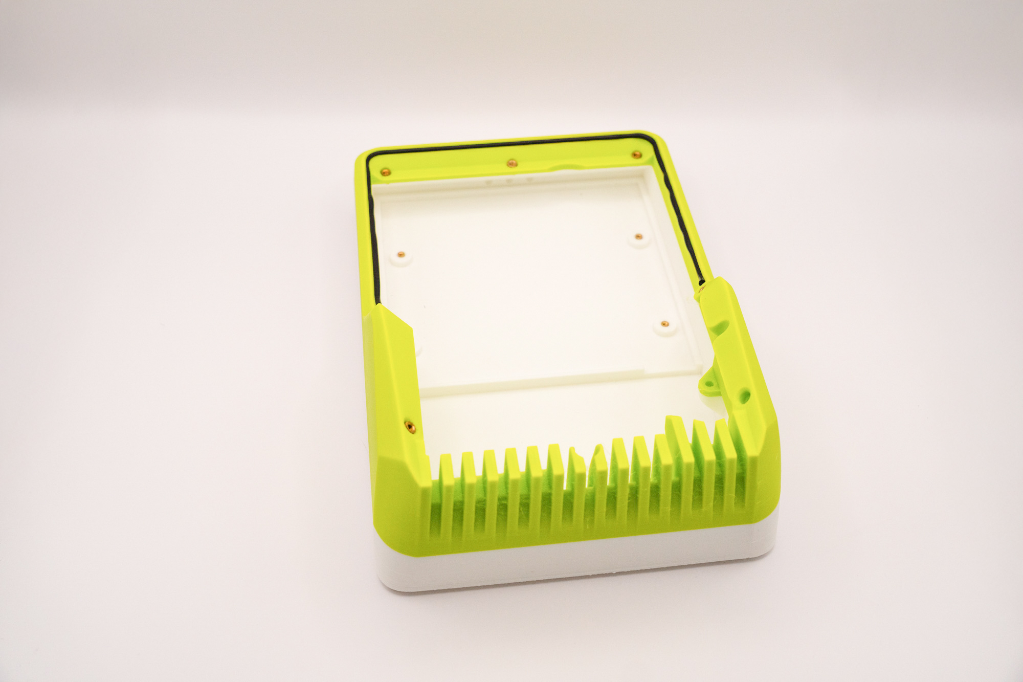
✅ Result
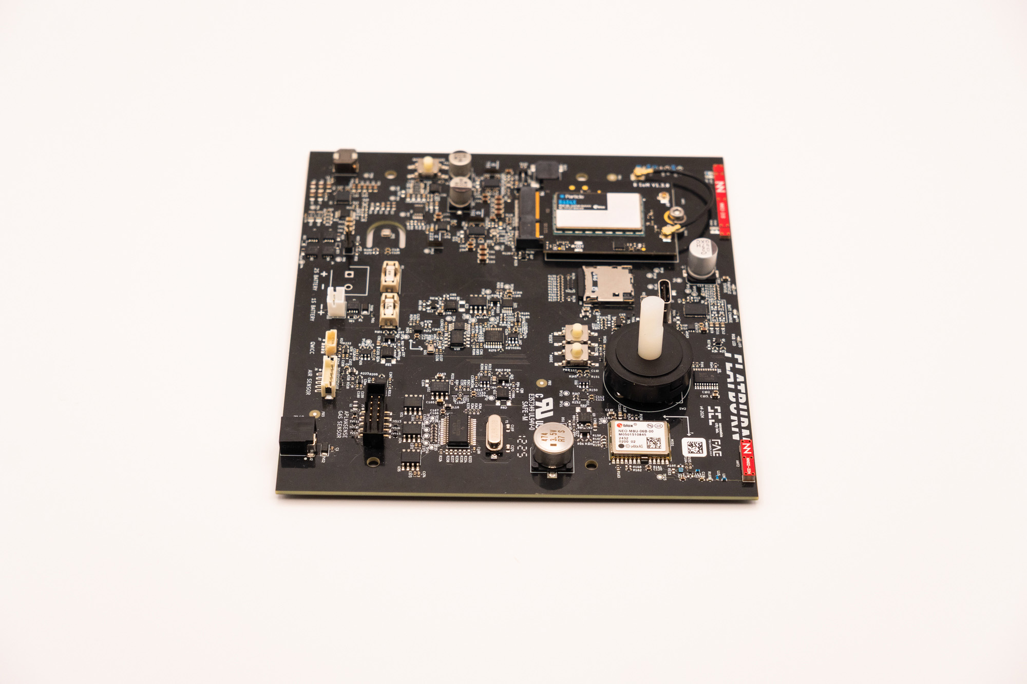
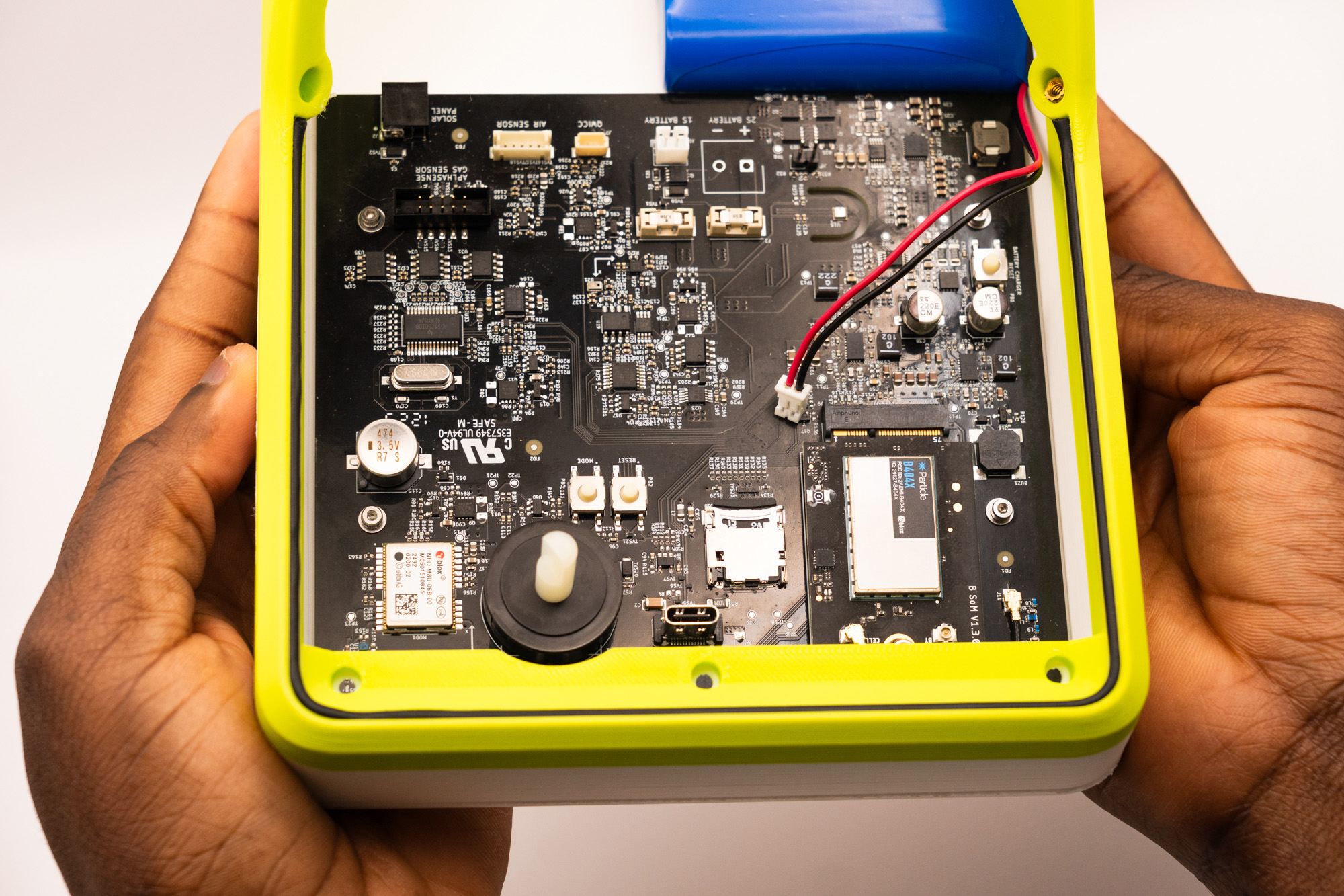
Step 6 – Populate Main Board
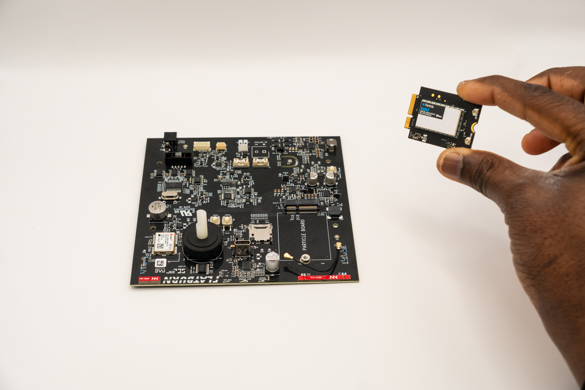
Remember to choose the type of Particle module (EMEA or US) according to where the device will be deployed.
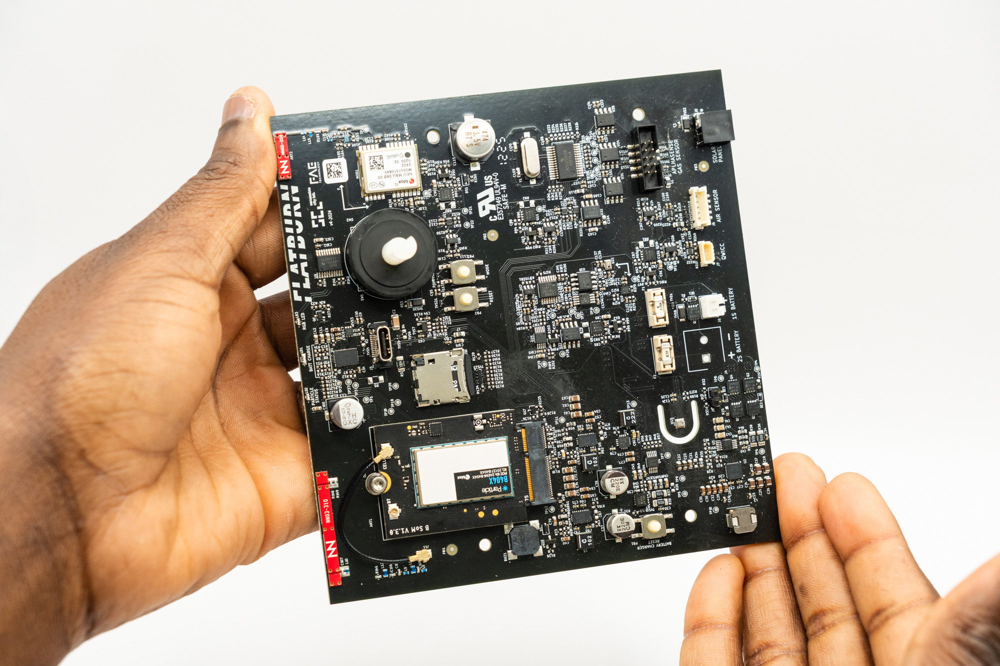
Insert the Particle module into the Main Board slot with its branding facing up:
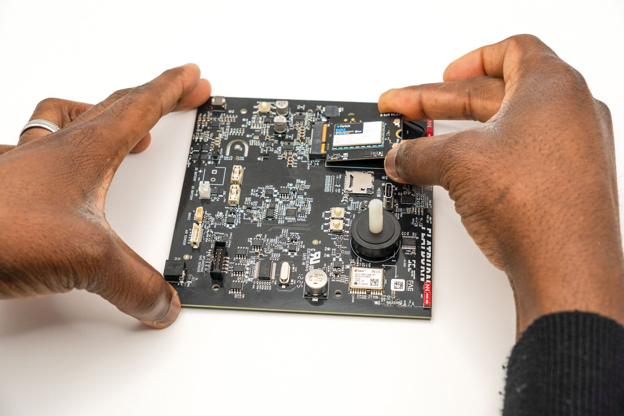
Fasten a M2.5x4 screw with a washer and bolt into the Main Board to secure the module:
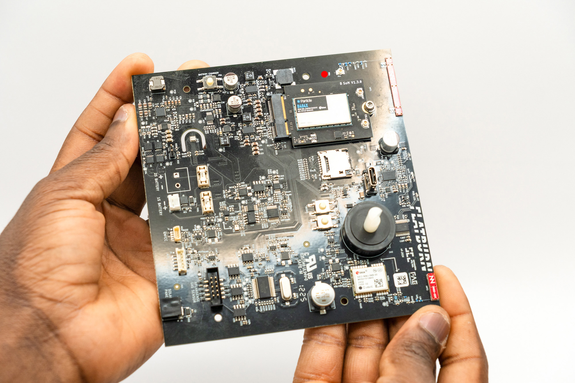
Now, pick the GSM antenna cable and connect it between the Particle module and the Main Board:
- Depending on the Particle module type, the antenna connector will be in different place (always signed with a CELL label).
- It can be tricky to snap the connector on. If needed, use a plier with care to not damage the connector and boards, pressing the connector from its front face, but never press from the sides because that will damage the connector.
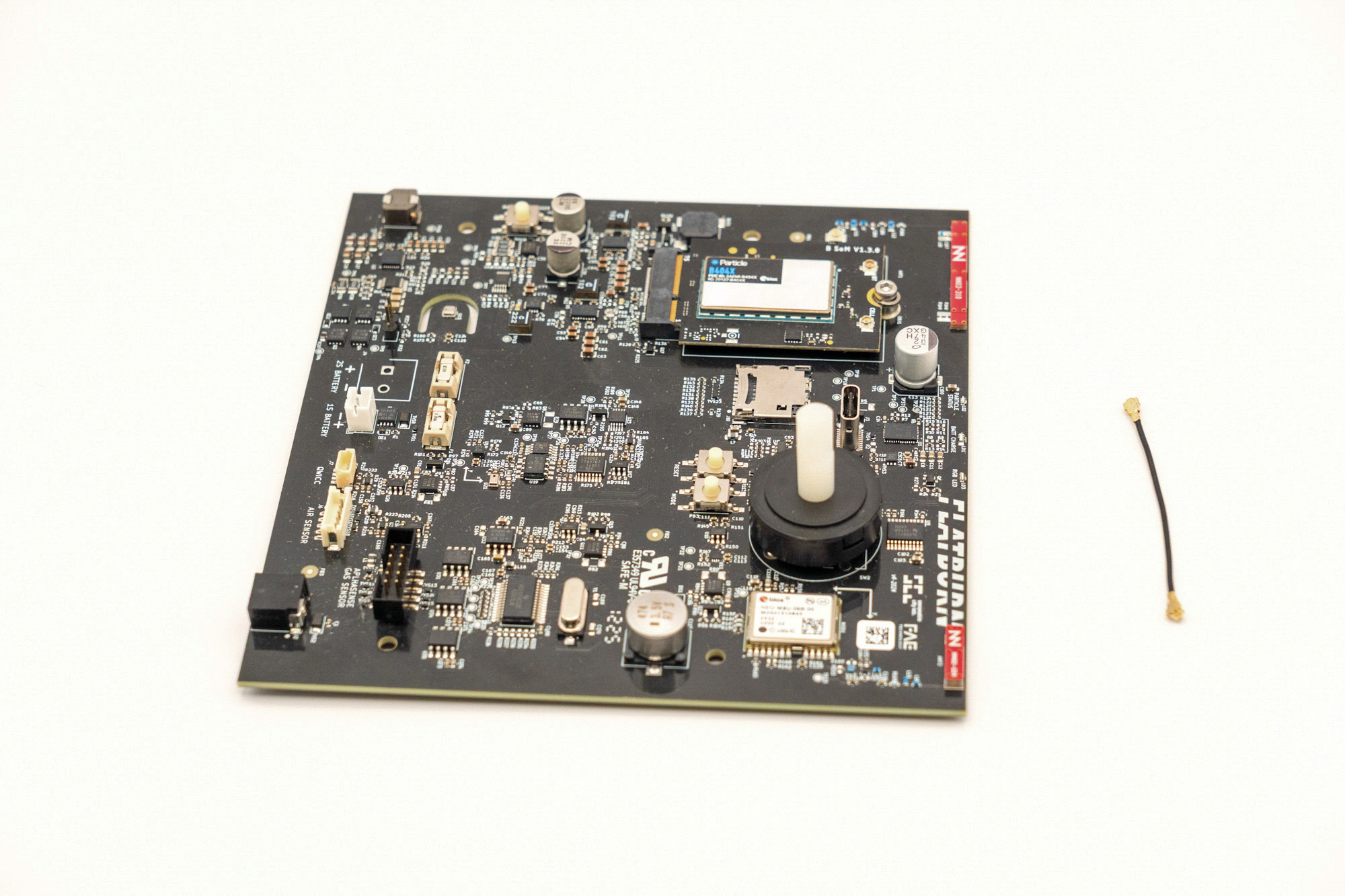
To finish, add the microSD card to the Main Board slot:
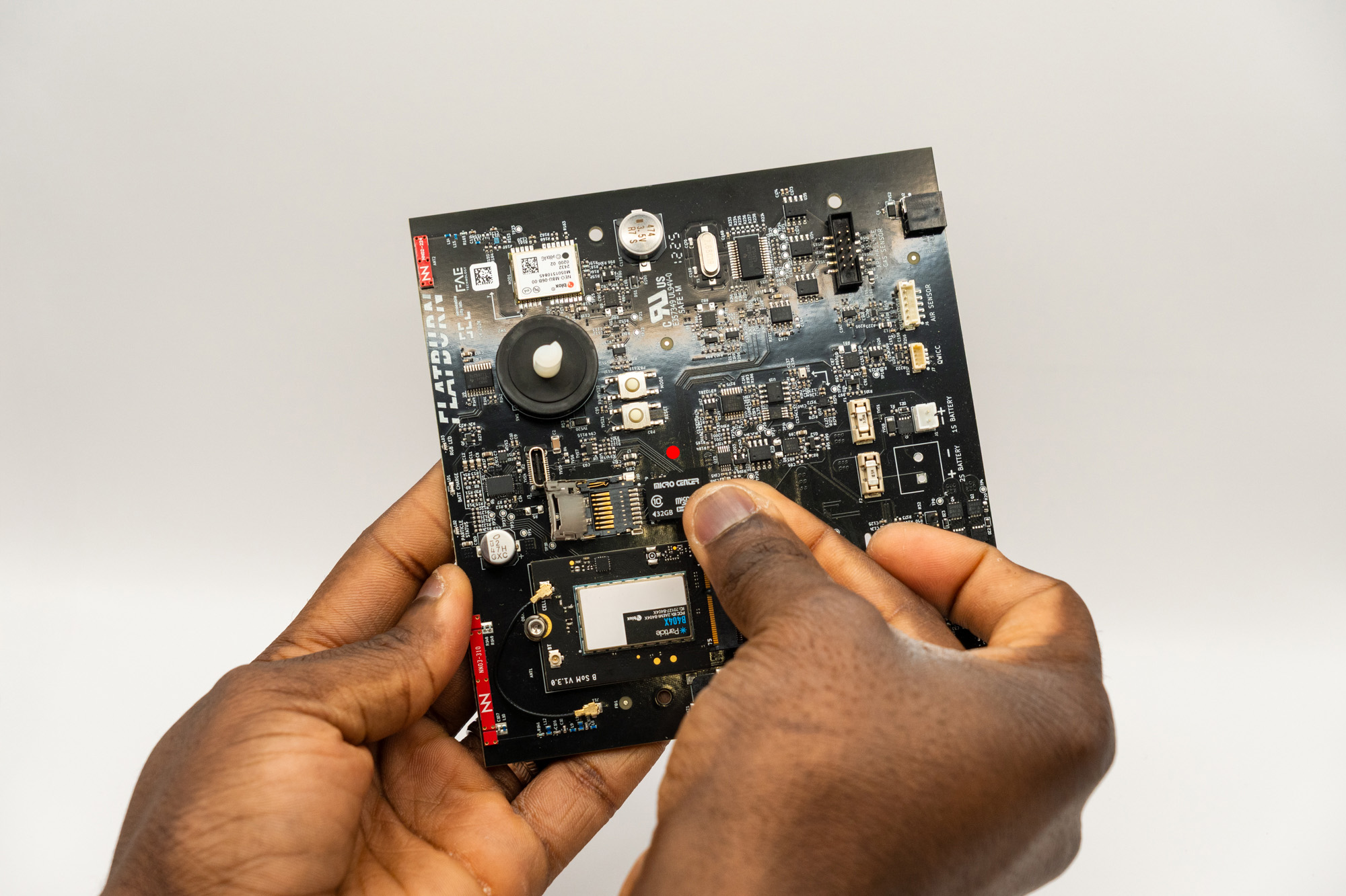
✅ Result
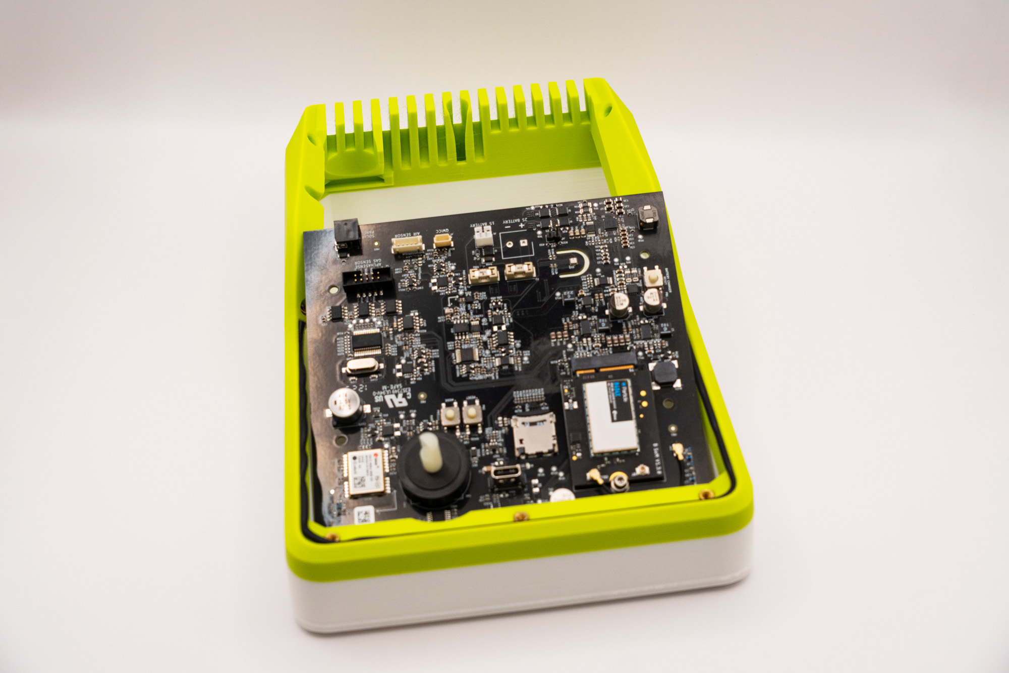
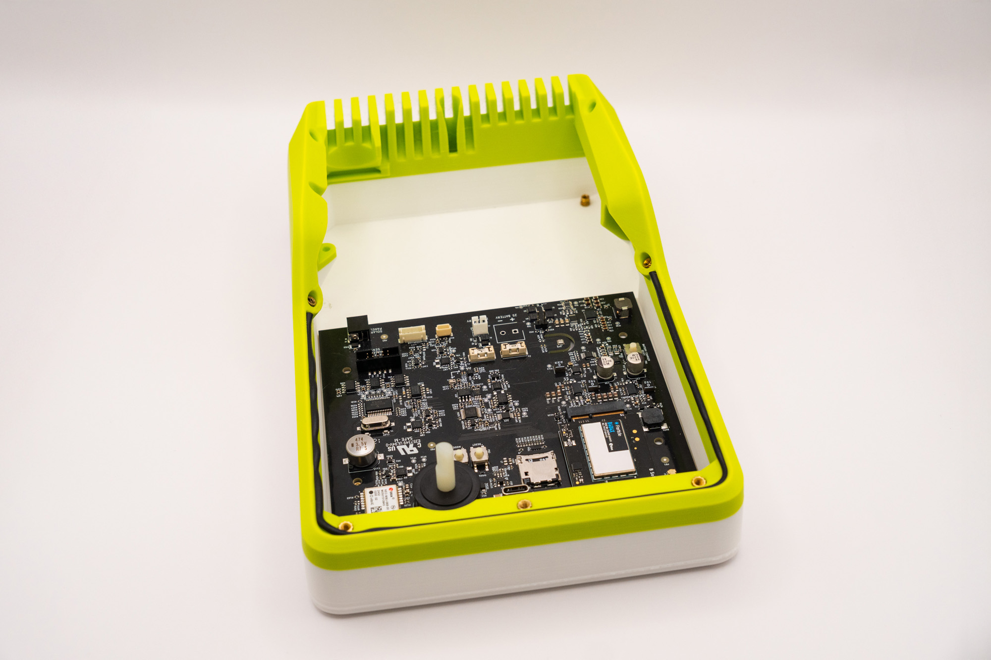
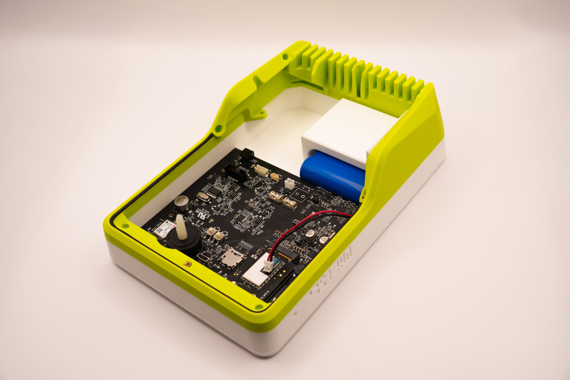
Step 7 – Battery and Main Board
To insert the Main Board into the top piece, first place its front edge against the top piece at an angle:
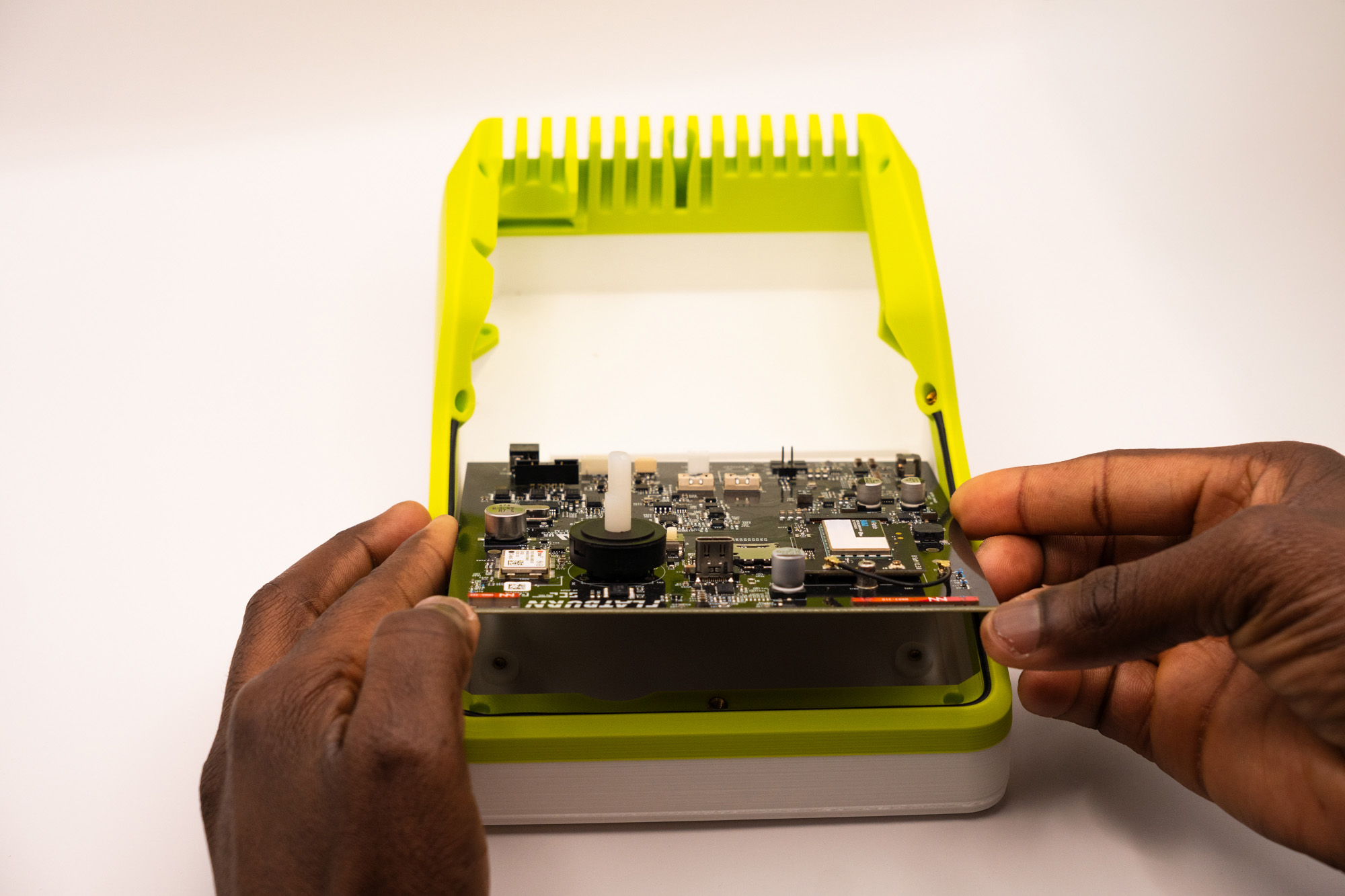
Finally, lower and then slide it back:
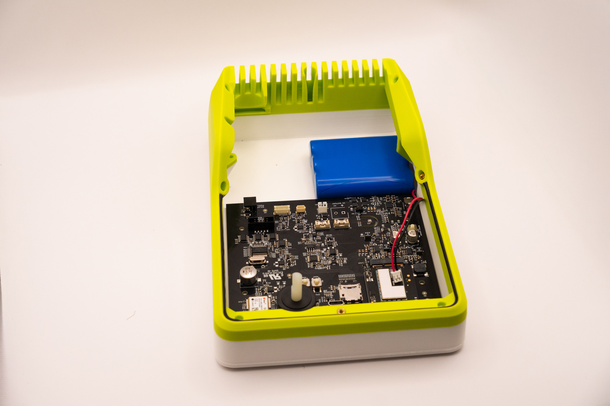
Place the battery on the top piece, making sure the cable orientation follows the image:
Then, add the battery_cover:
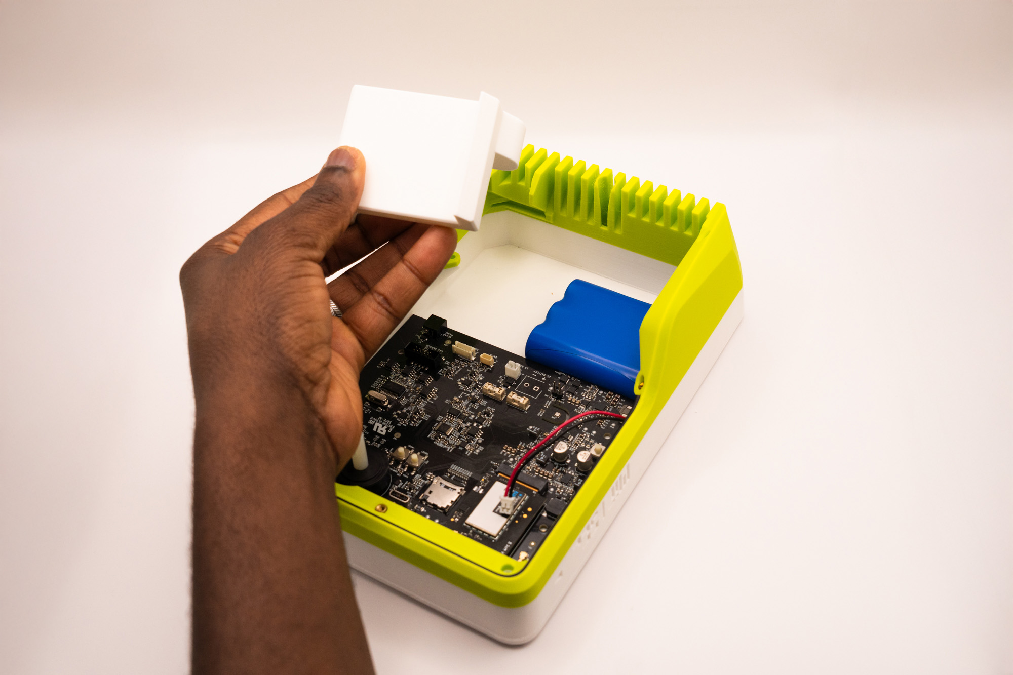
✅ Result
Step 8 – Secure Main Board
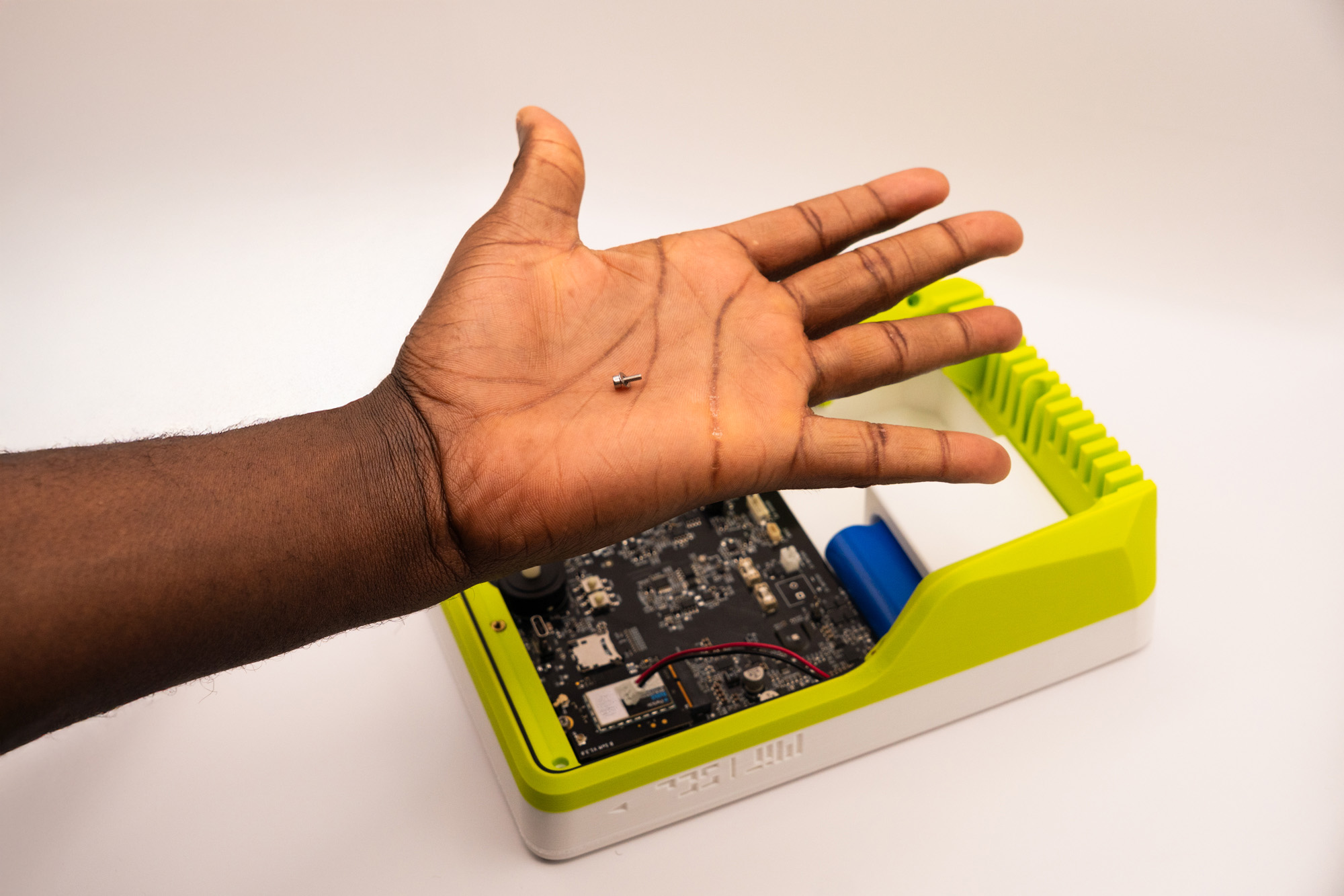
For fixing the Main Board, pick four M2 washers and put each into four M2X6 screws
Fasten them into the four indicated holes:
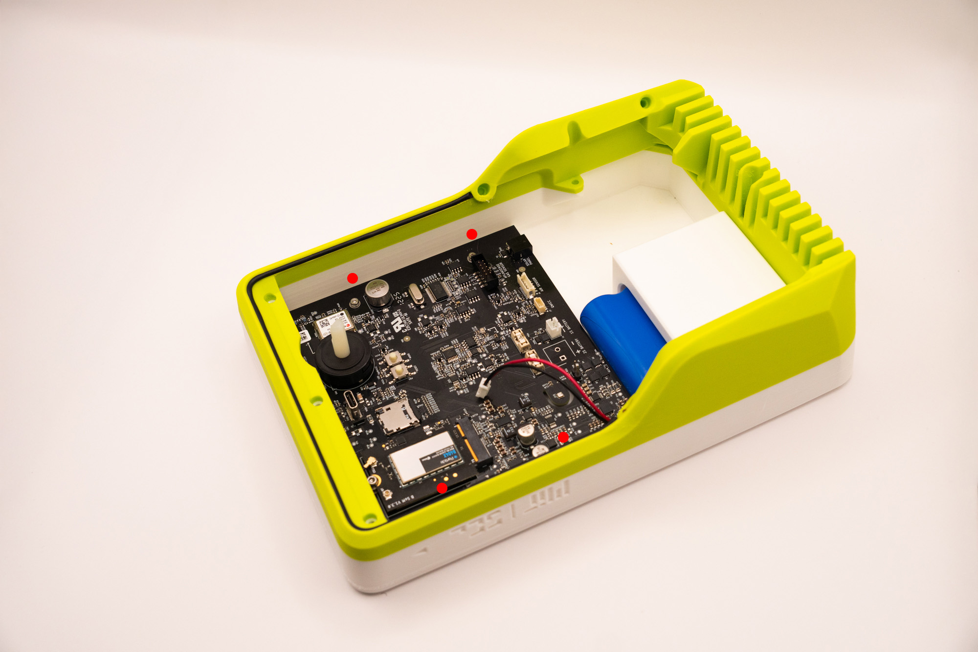
✅ Result
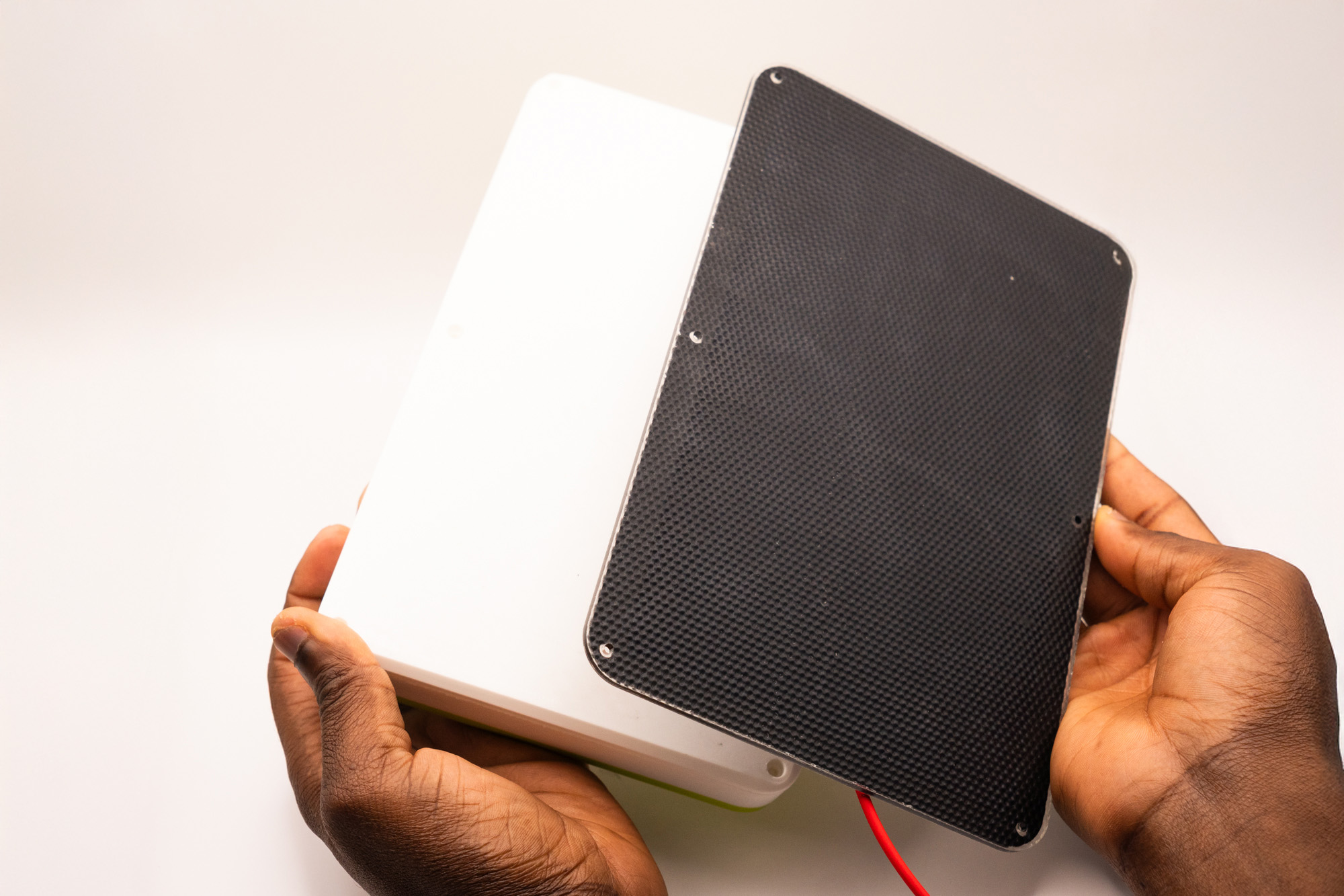
Step 9 – Solar Panel & Gas
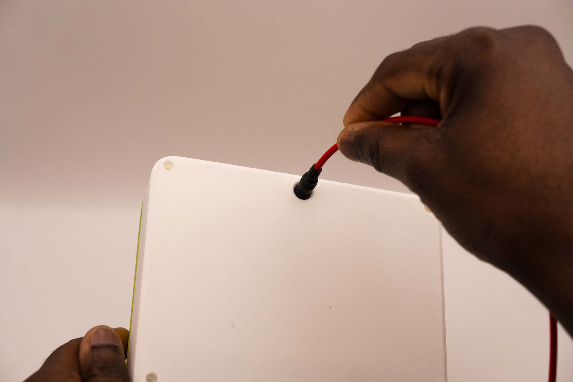
Align the panel to make sure the cable is going out backwards, then pass it through the hole:
Pick up six M3X16 screws, six M3 washers, and six 5mm spacers. These will be used to secure the solar panel to the top piece in the six holes.
The correct order is screw → washer → Solar Panel → spacer → top piece:
Start with both the intermediary holes, since that will make it easier to align the Solar Panel to the top piece:
Proceed to the corners:
Due to variation of manufacturing tolerances, it might be harder to fasten these corner screws.
Make sure the screw is properly aligned to the insert on the top piece and fasten while making sure it is following the right angle.
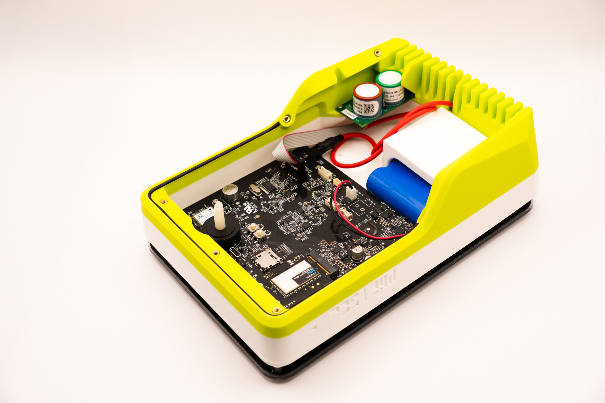
✅ Result
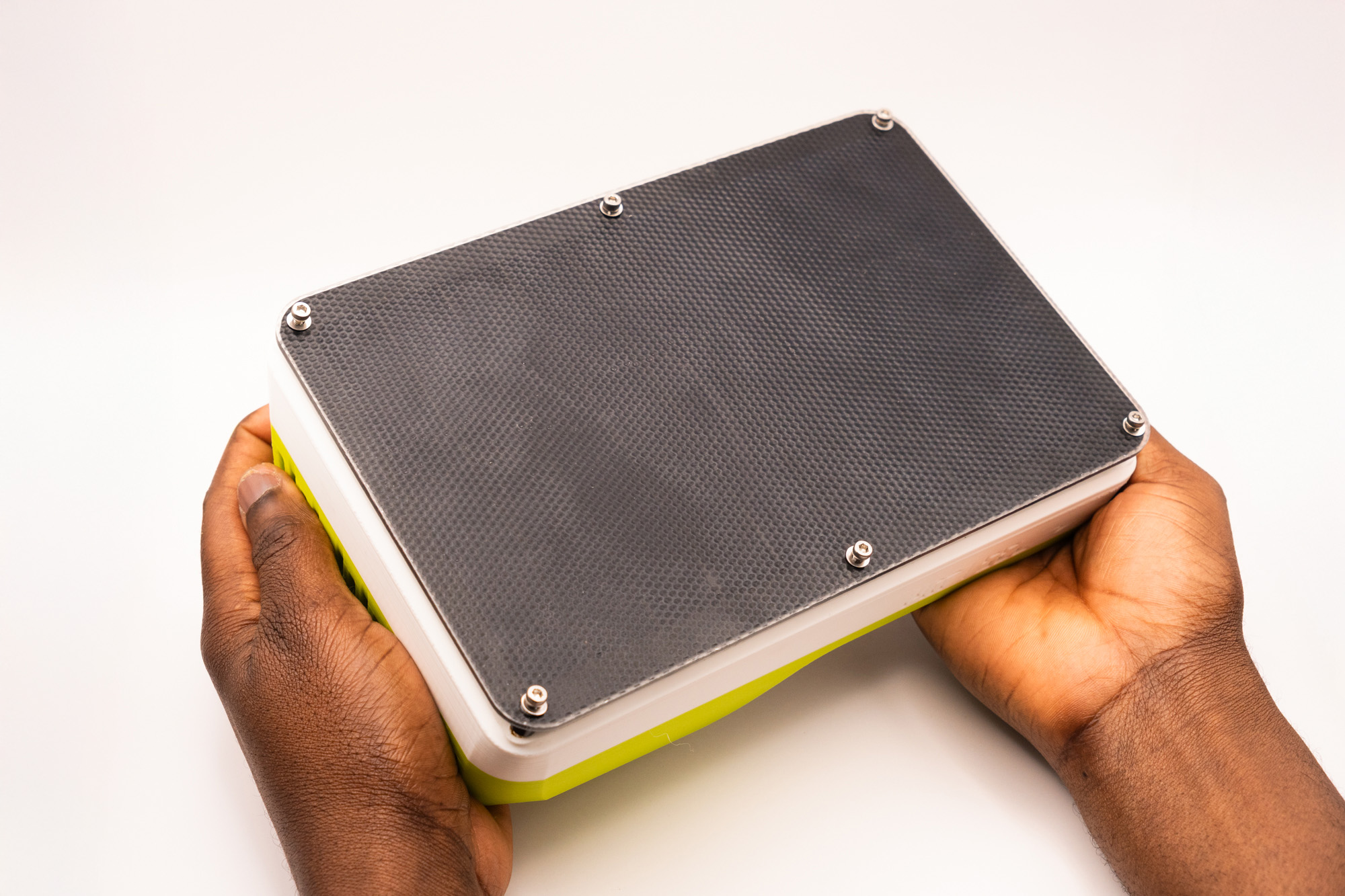
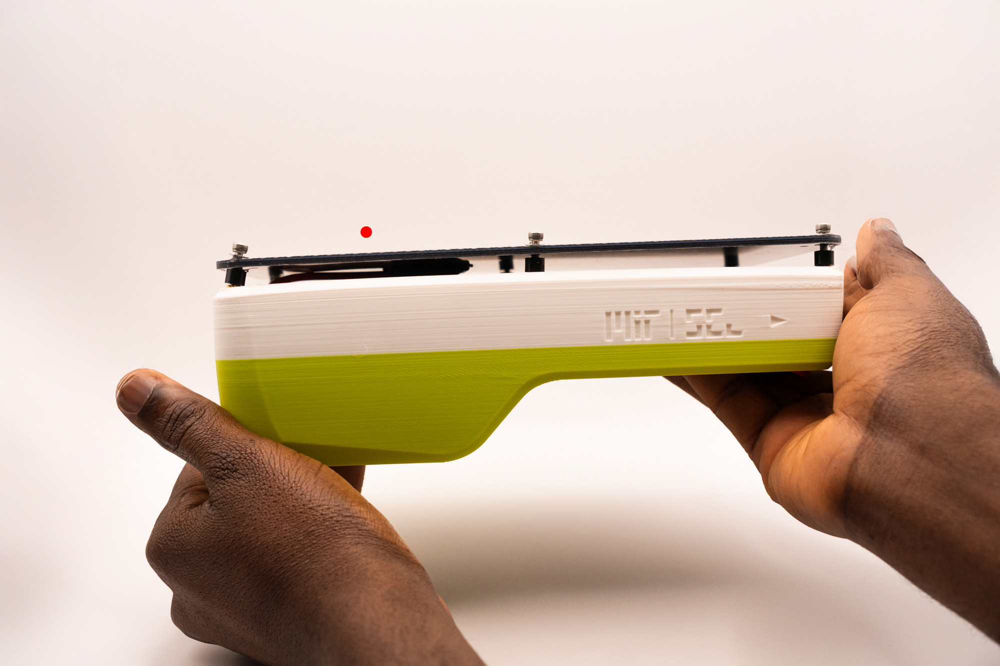
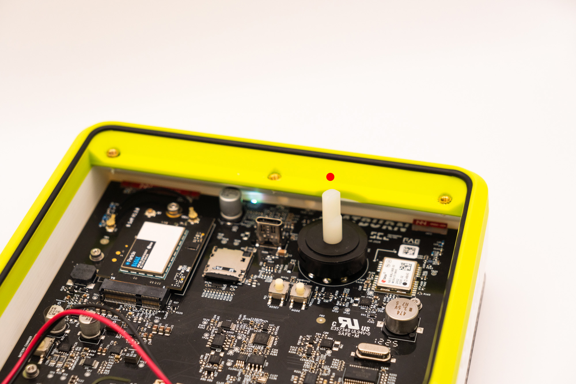
Please make sure there is no surplus of cable above the top piece, all excess should be below:
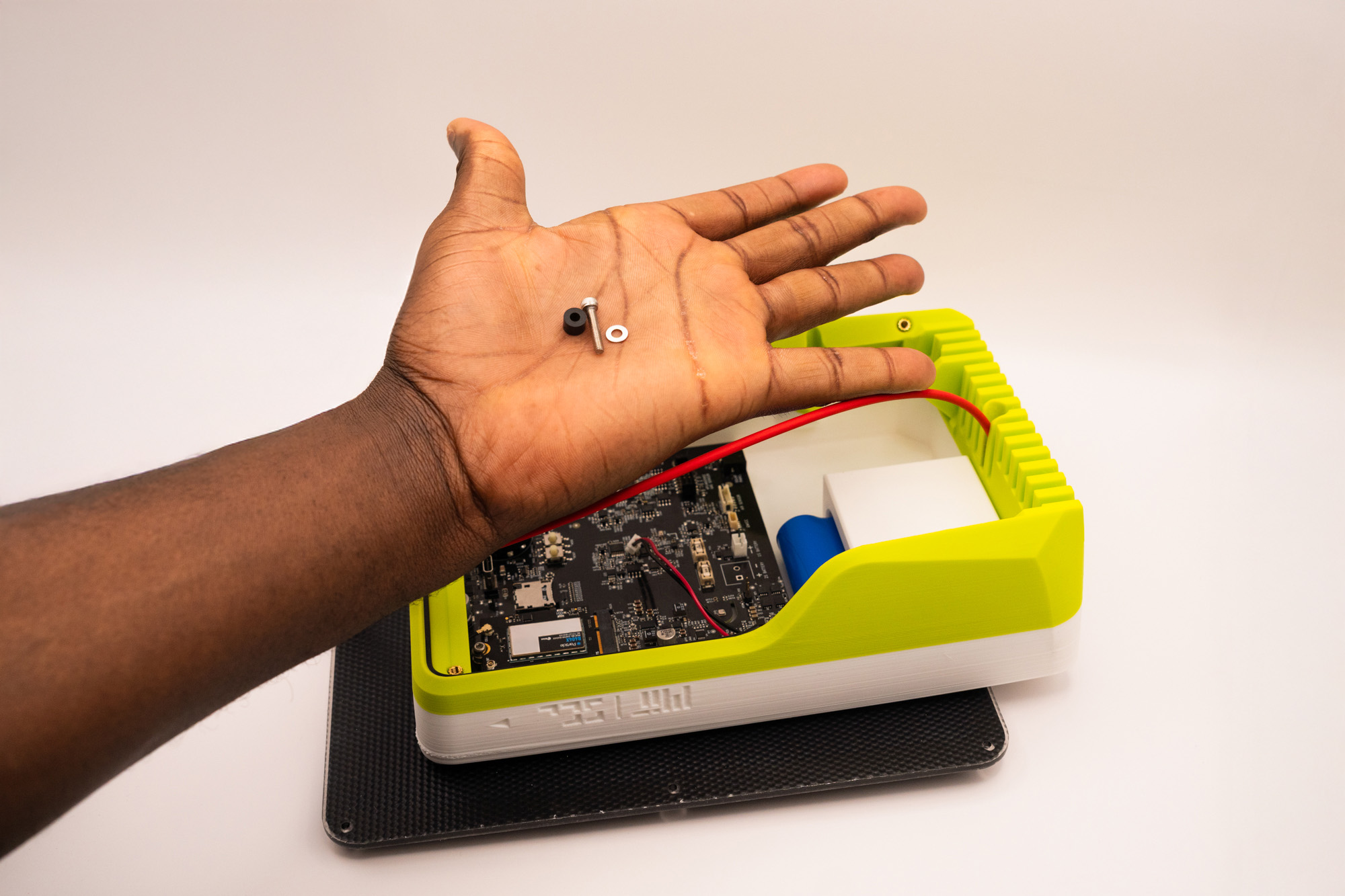
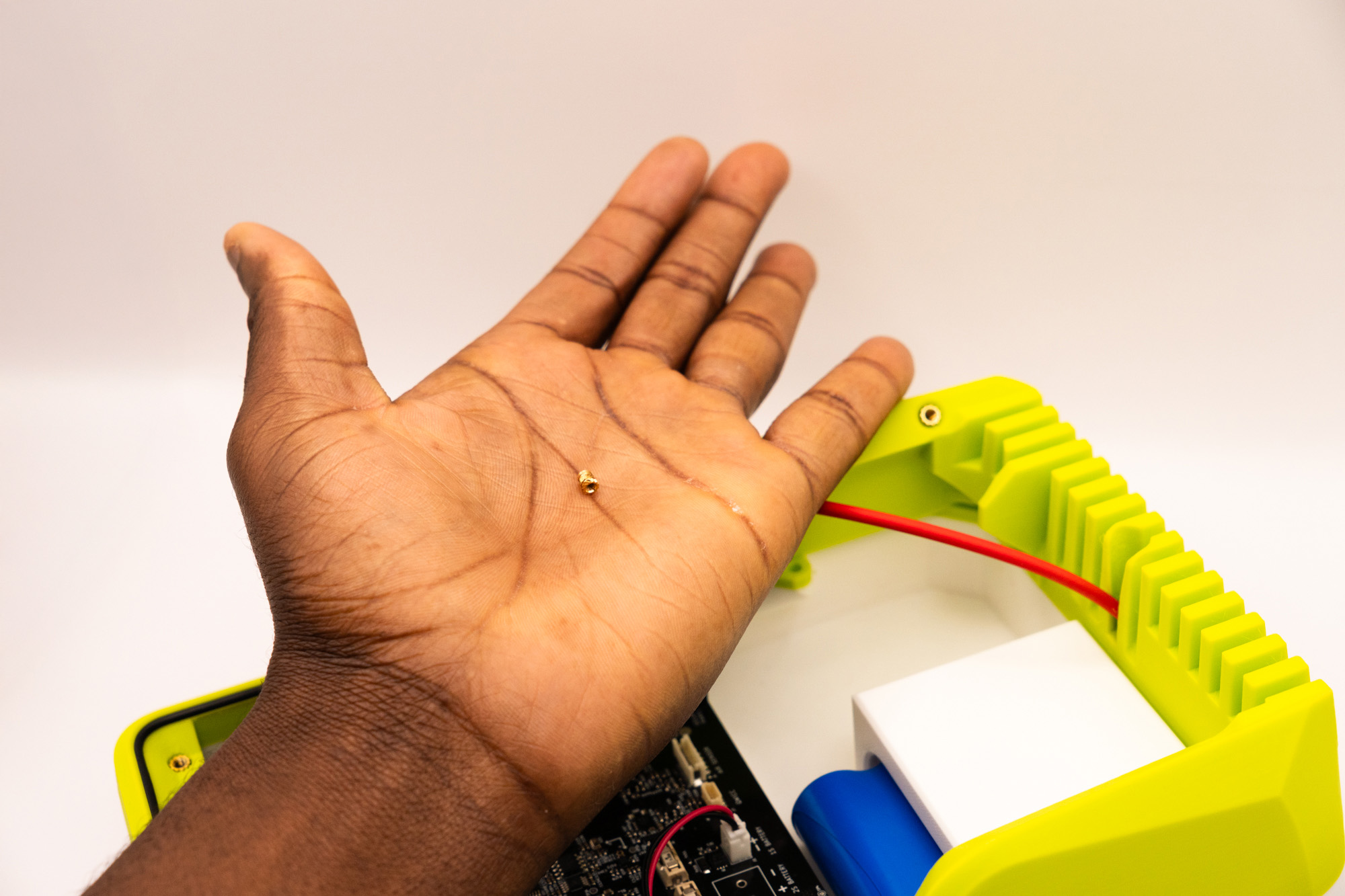
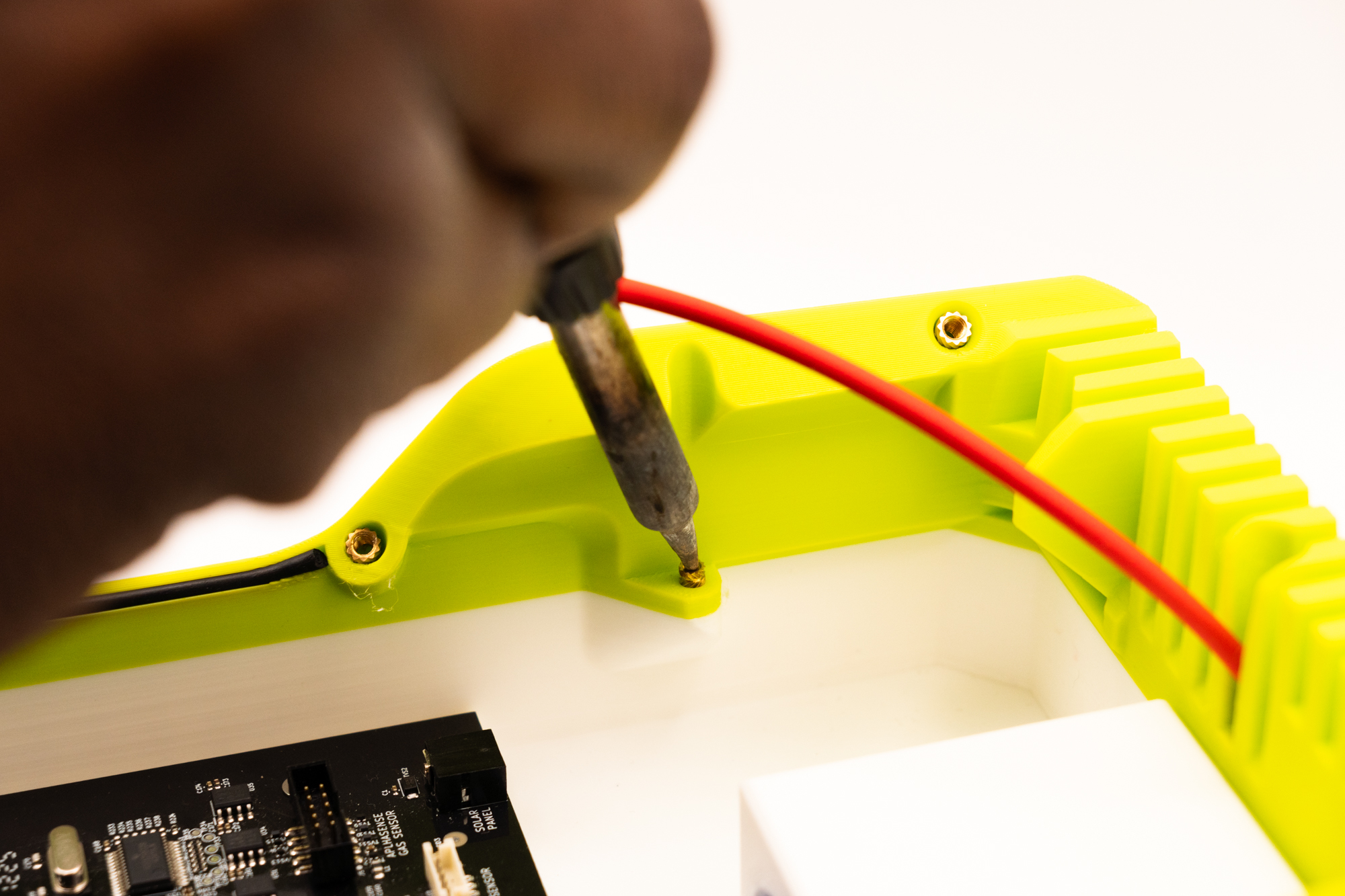
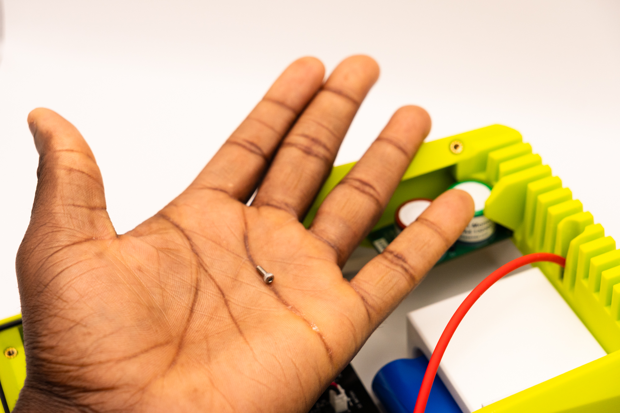
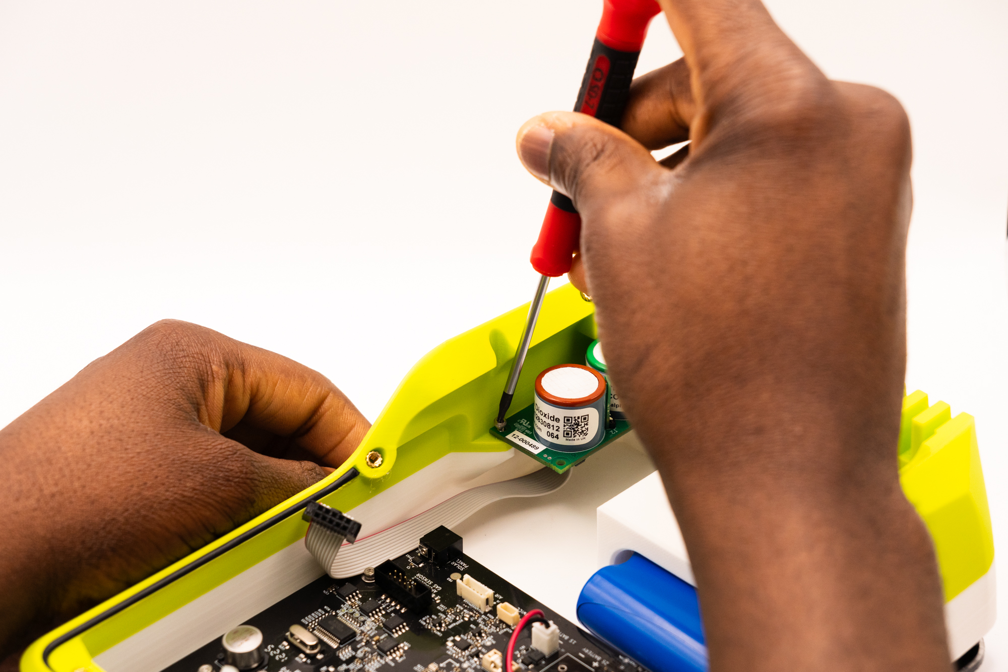
Pick up a M2 washer, and solder into the hole.
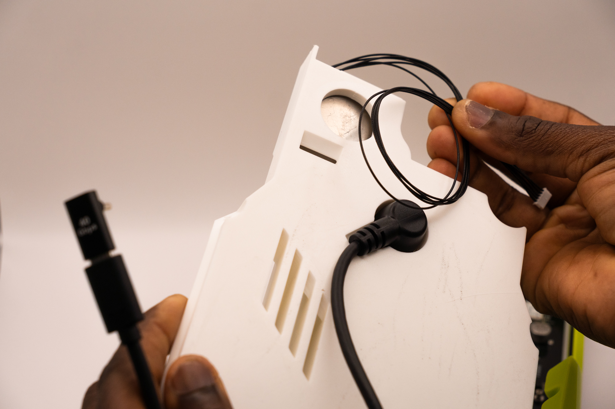
Pick up the gas and cable, and gently attach the pieces together.
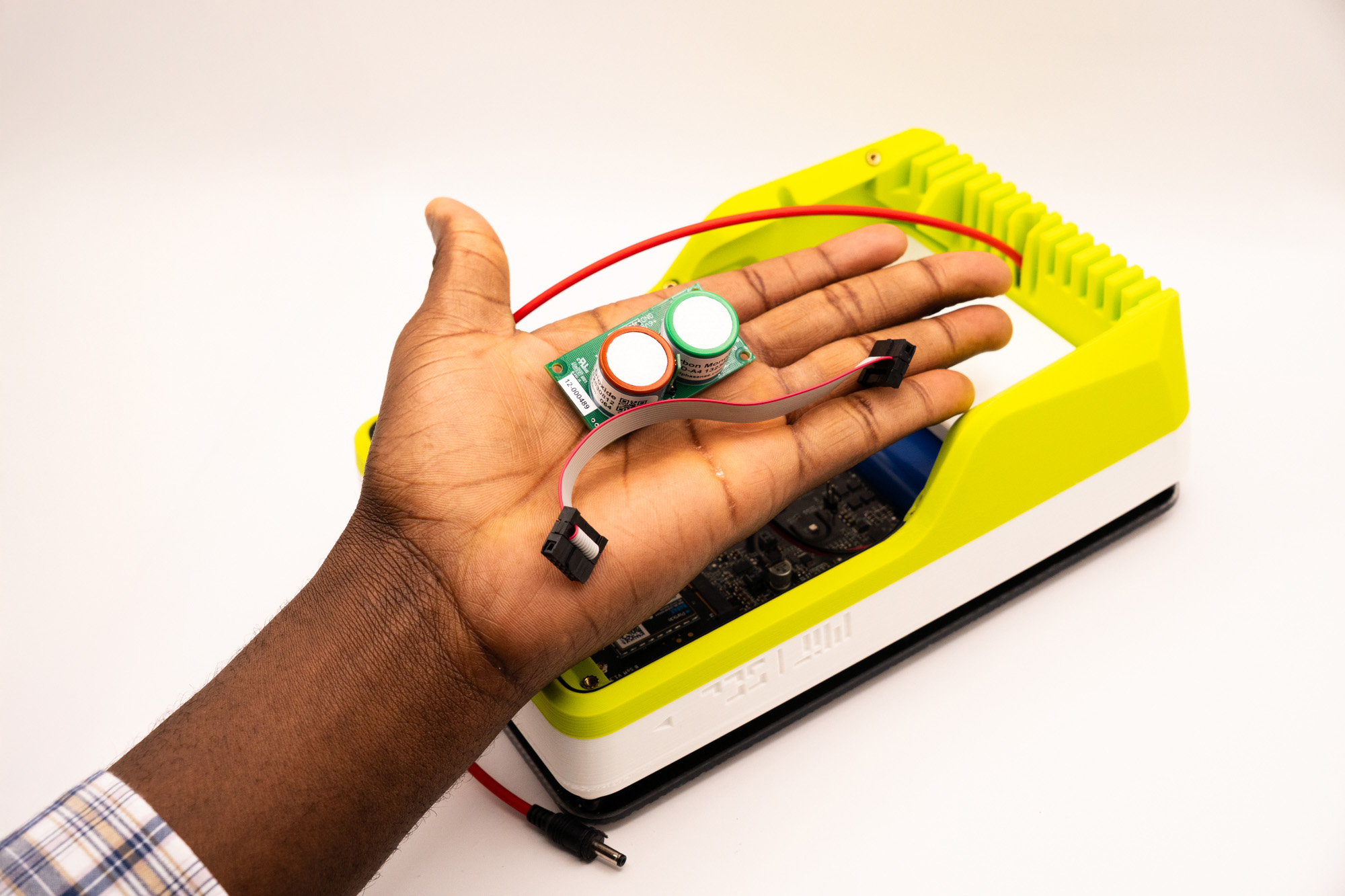
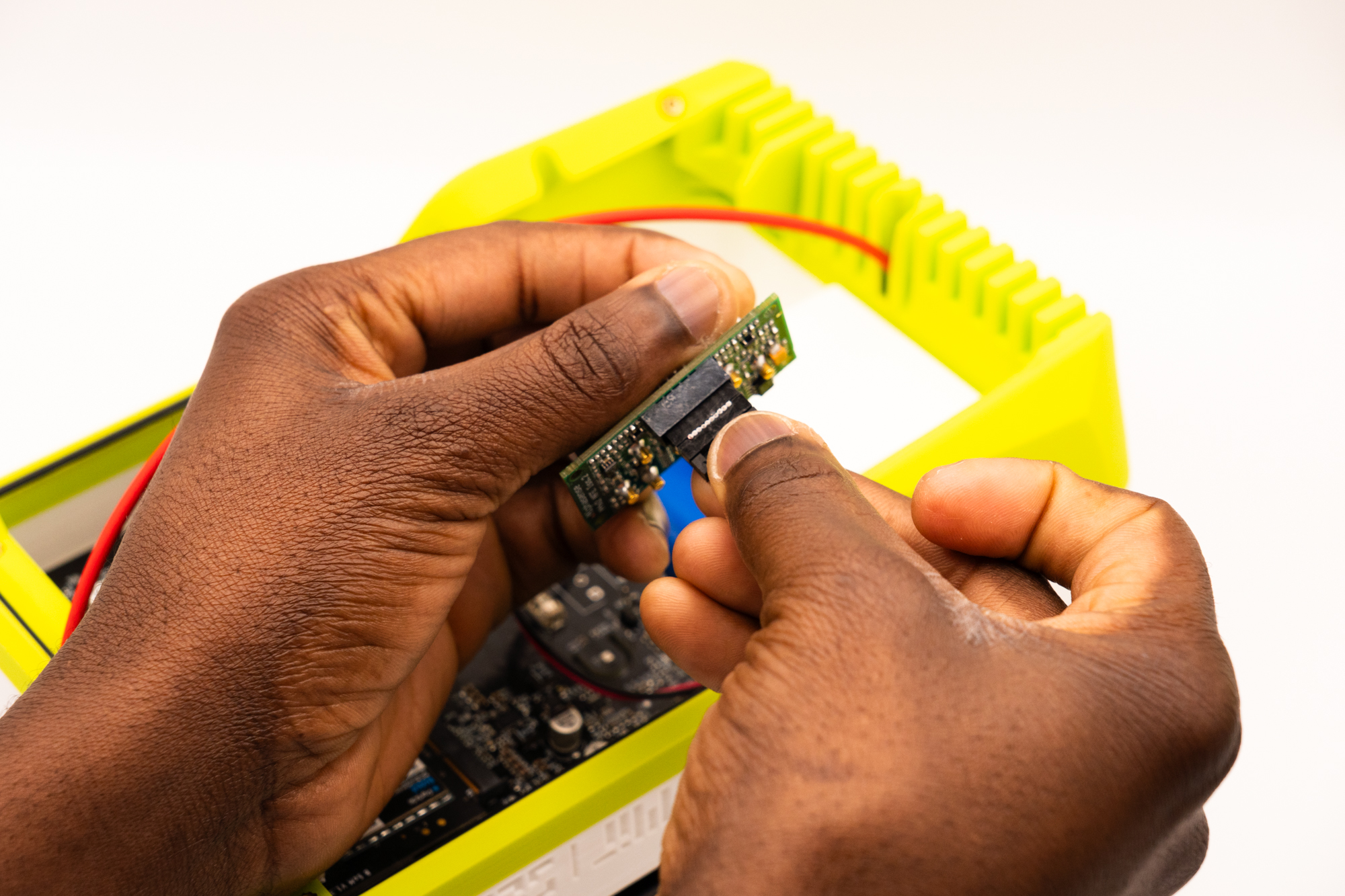
Push the gas into the corner so it sits on the ledge.
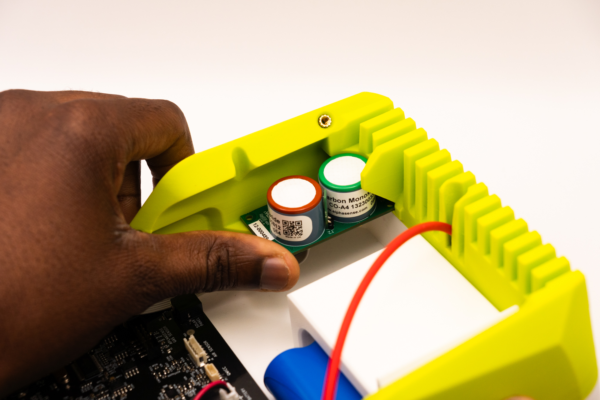
Pick up a M2 screw to attach the gas into place.
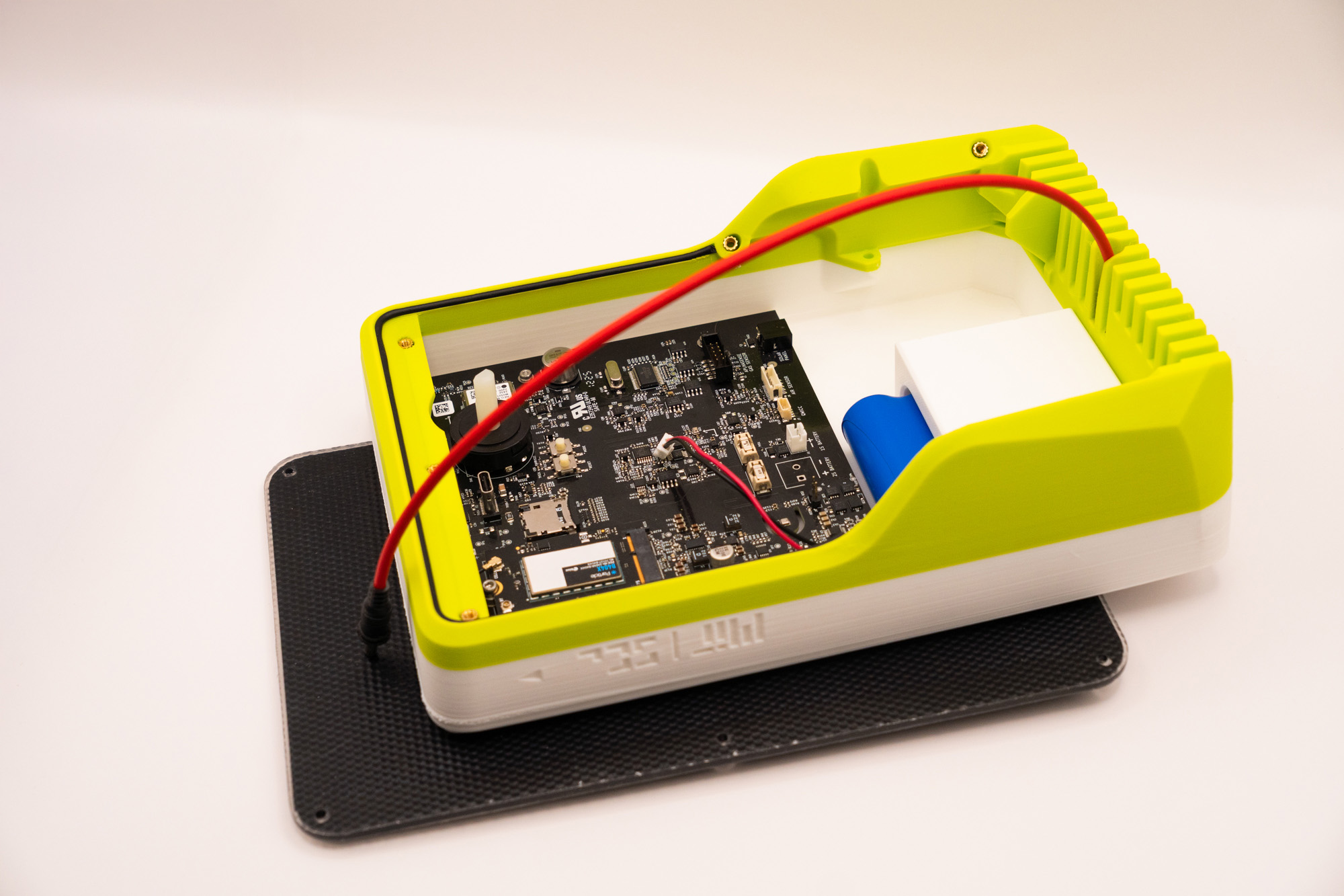
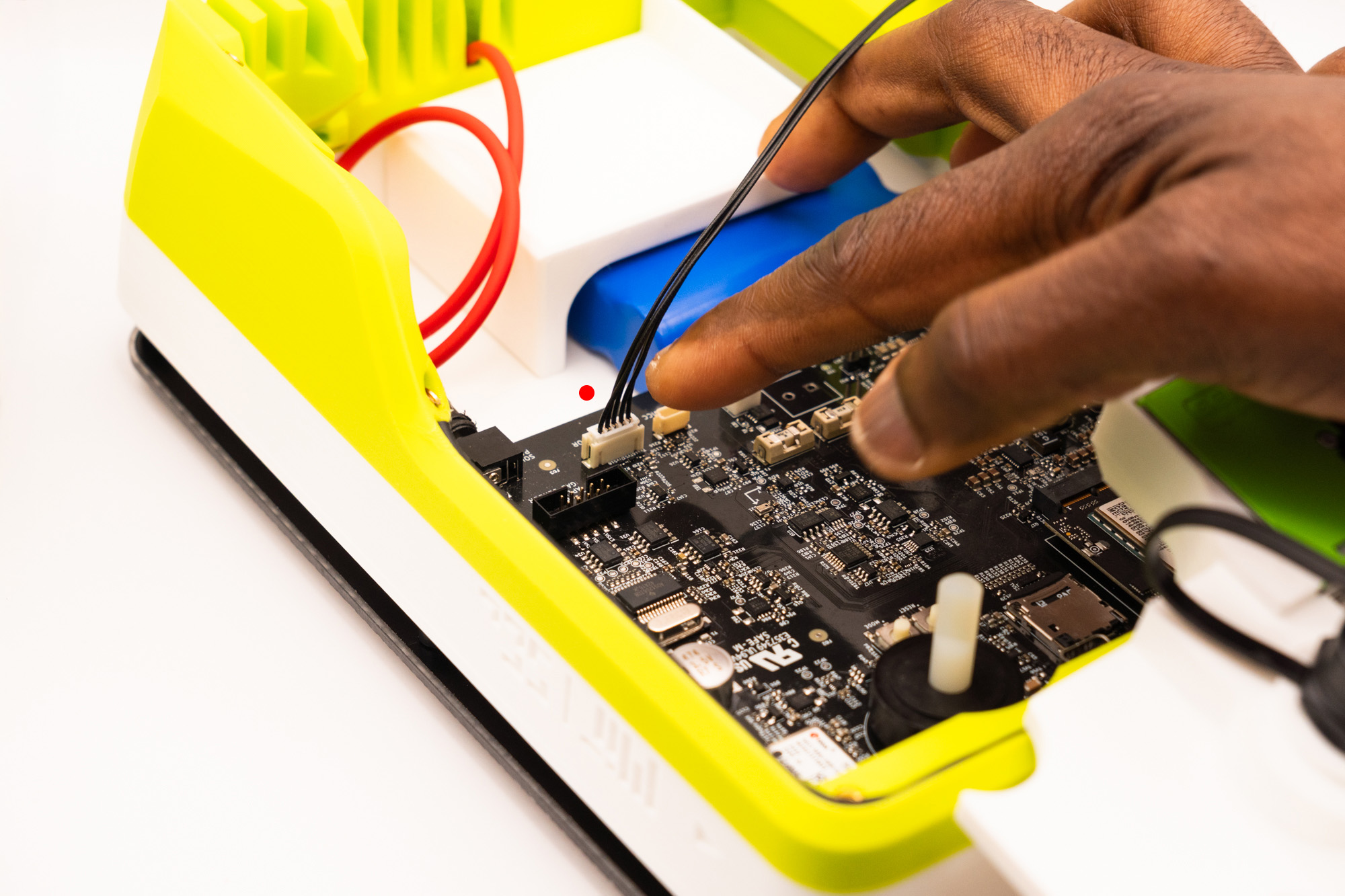
Attach the connector to the Main Board socket
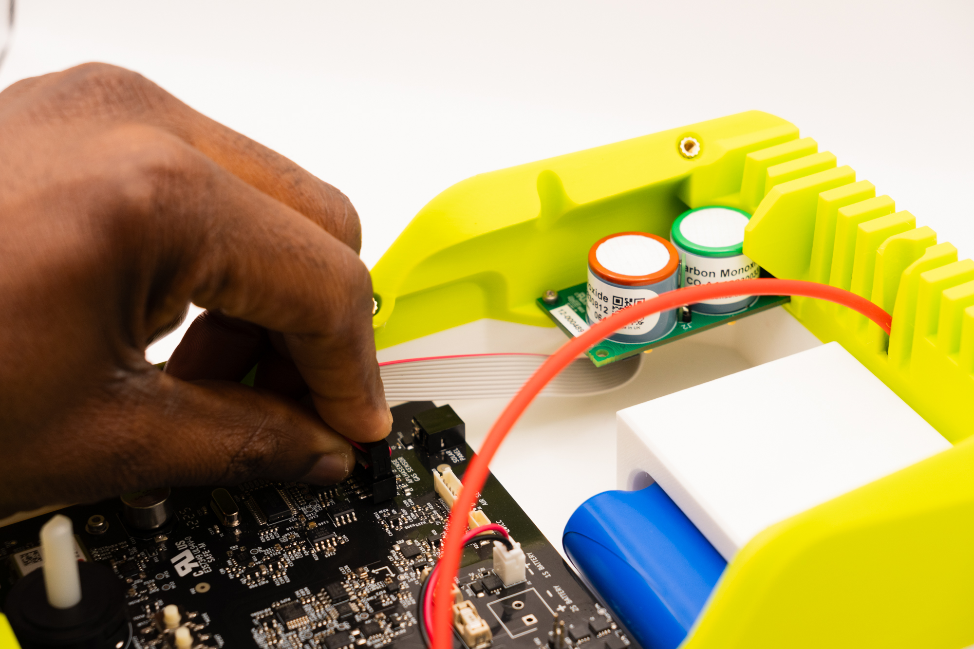
Gently wind the cable while making sure it enters through the indicated spot on the back of the top piece:
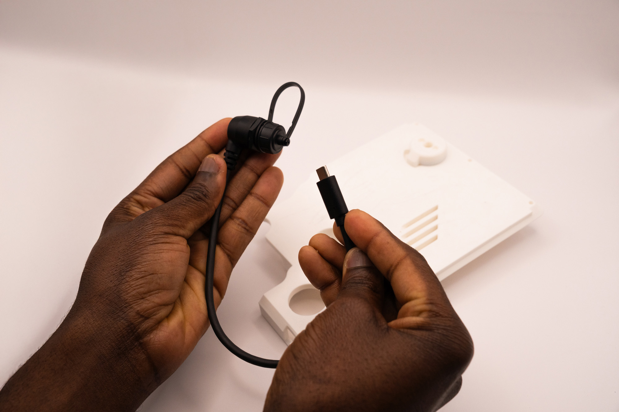
Step 10 – USB-C Cable
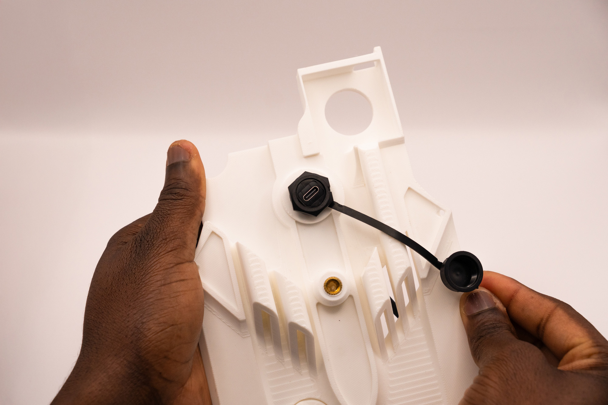
Pick up the Waterproof USB-C cable:
Now, unscrew the cap and nut, remove them completely leaving the rubber seal, then put the rubber seal back:
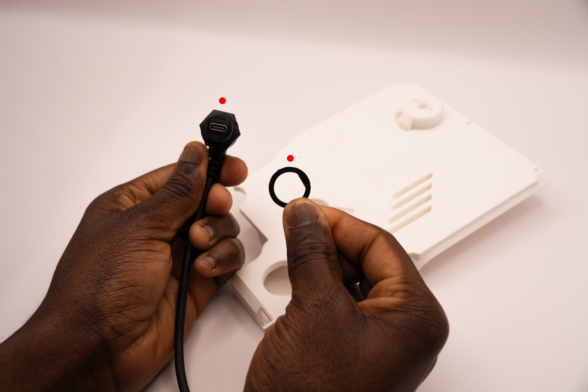
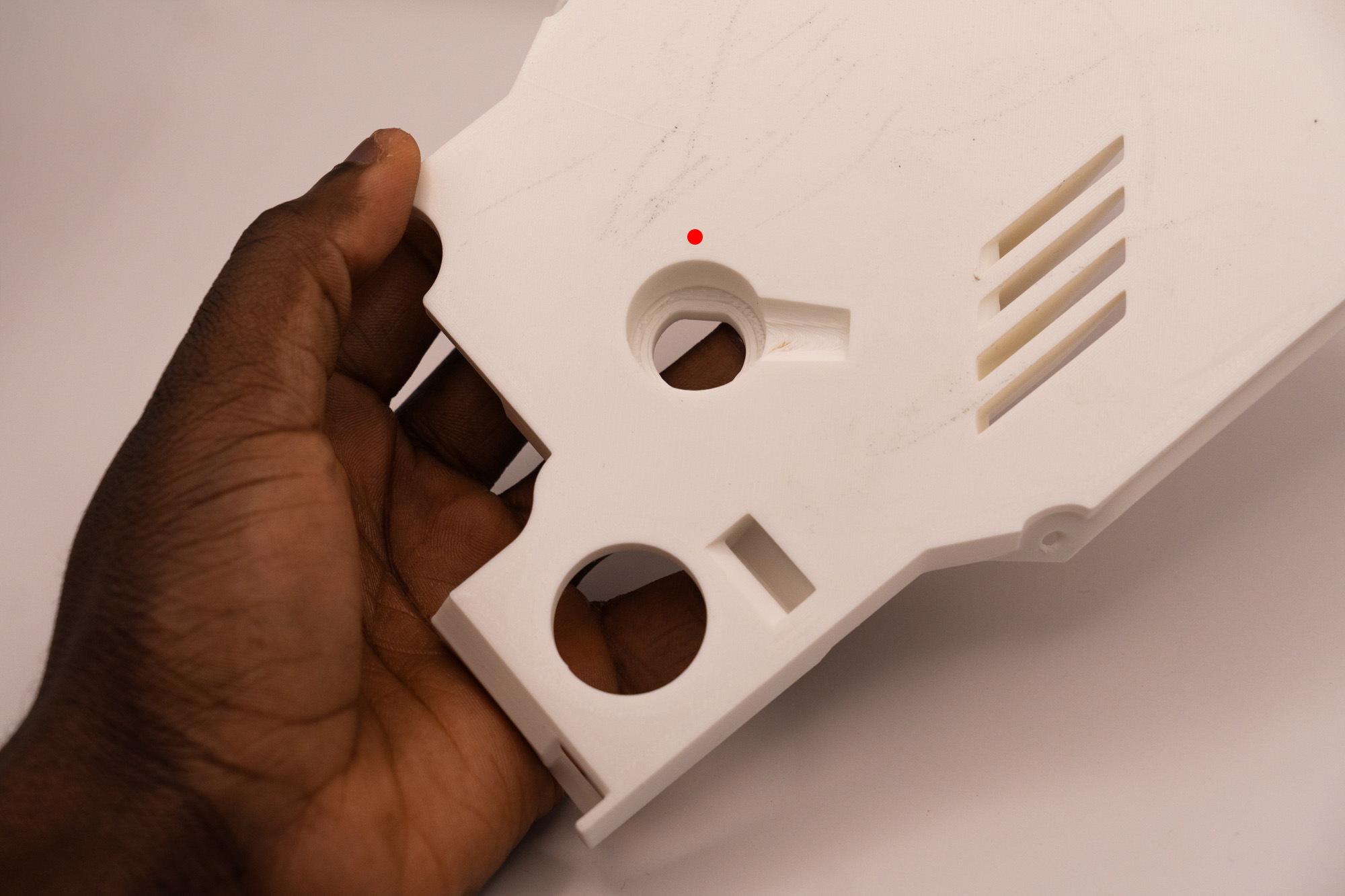
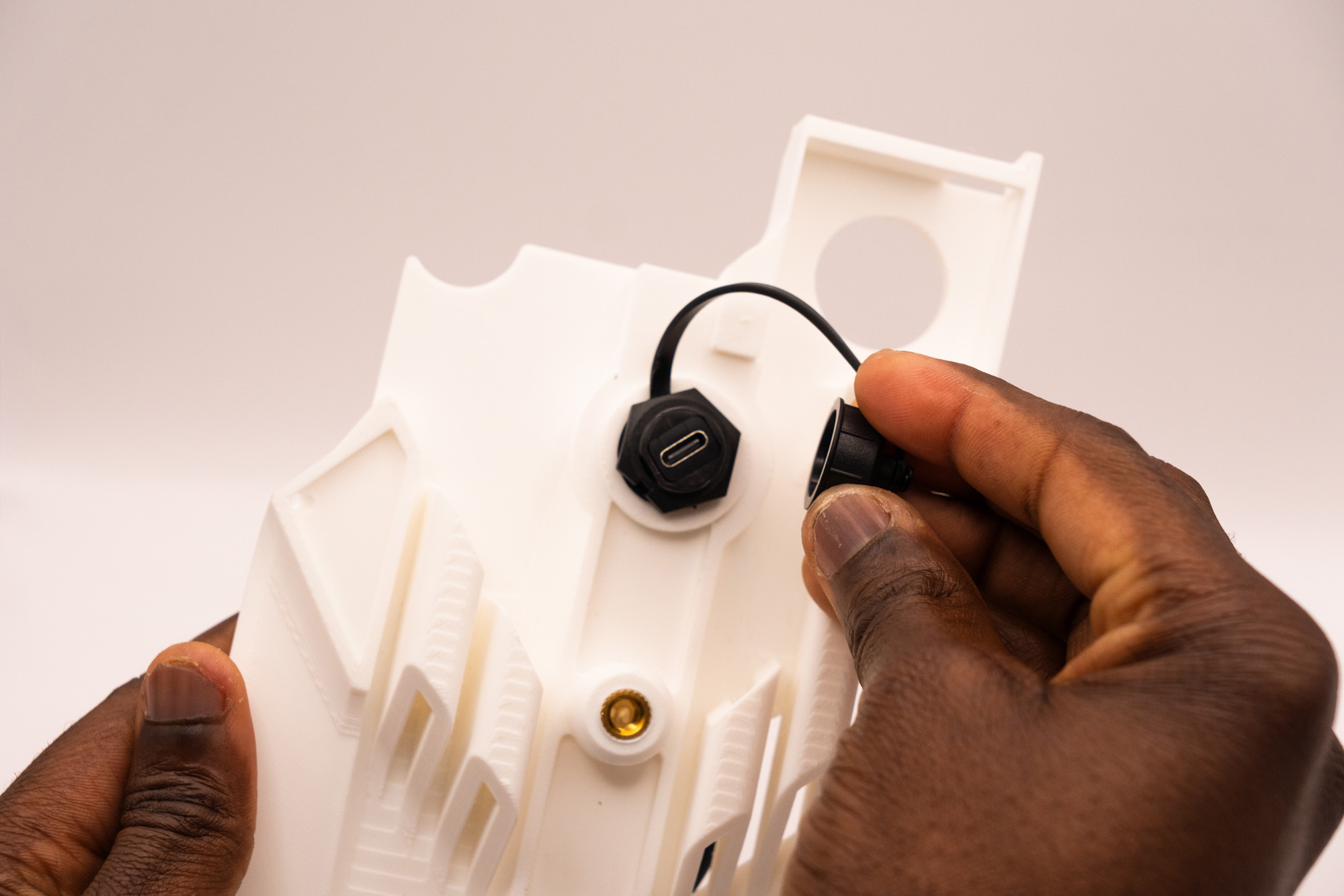
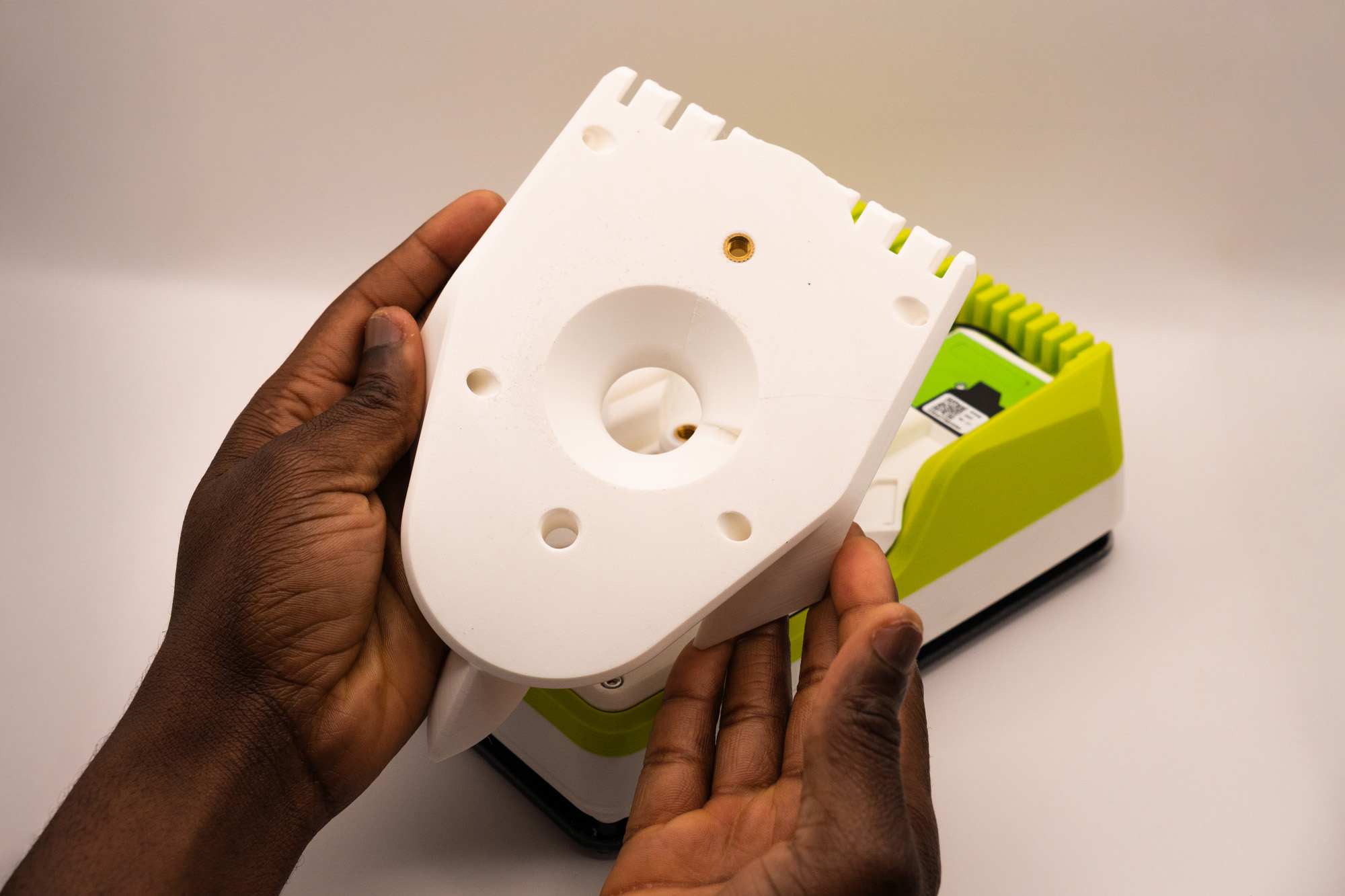
Place the cable in the appropriate place respecting the correct order of cable screw → rubber ring → middle piece:
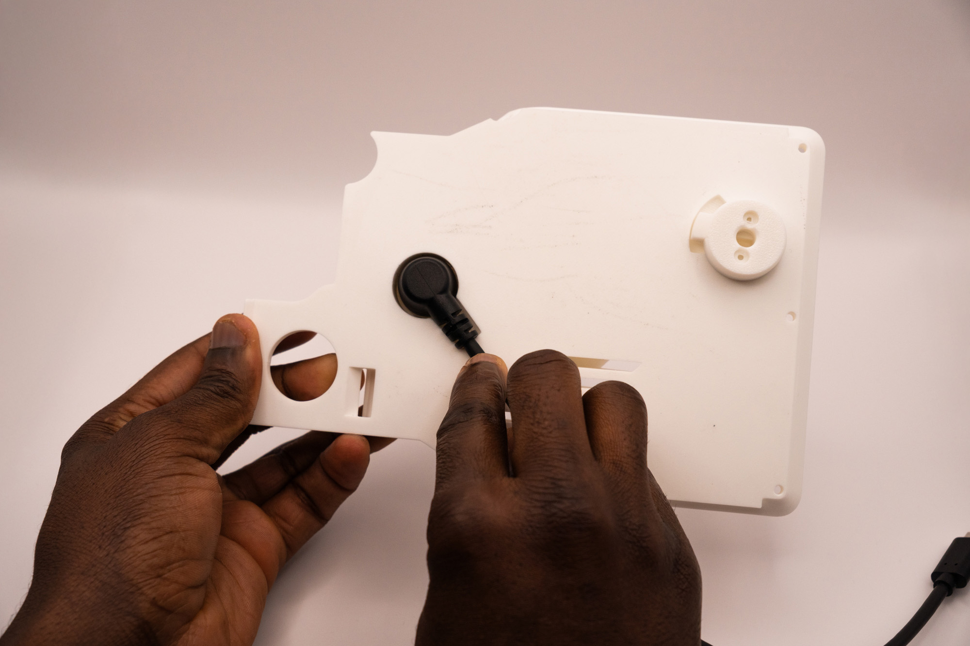
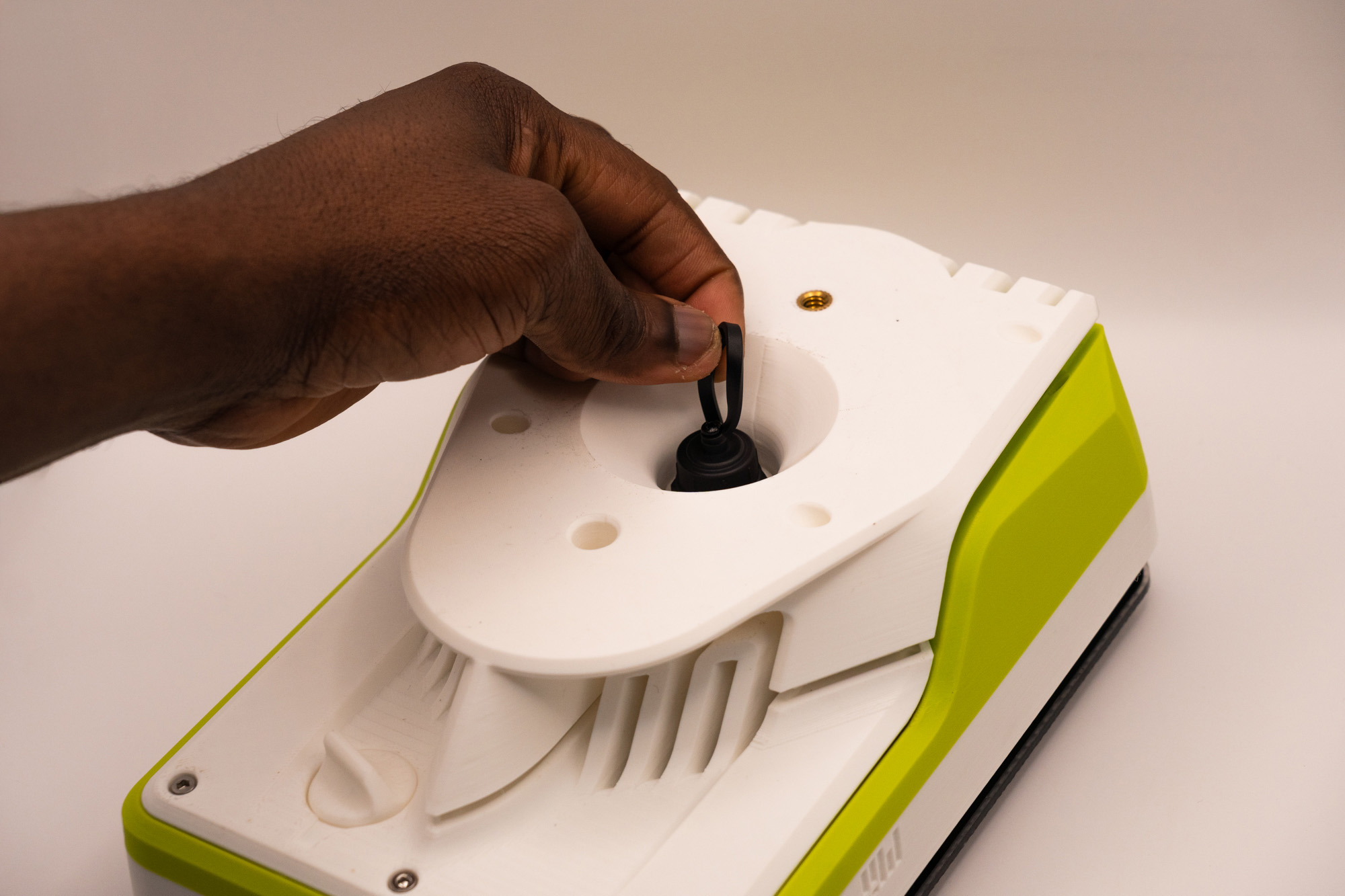
While holding everything together, turn the middle piece around and add the cap ring, leaving its strip pointing to the right.
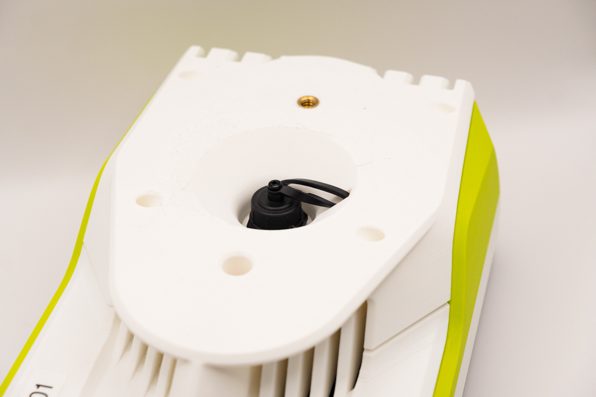
Fasten the nut while keeping the cap strip at the same position:
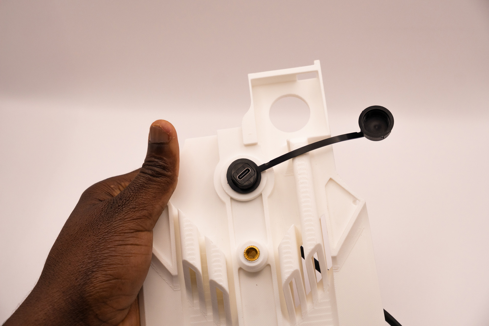
Screw the cap:
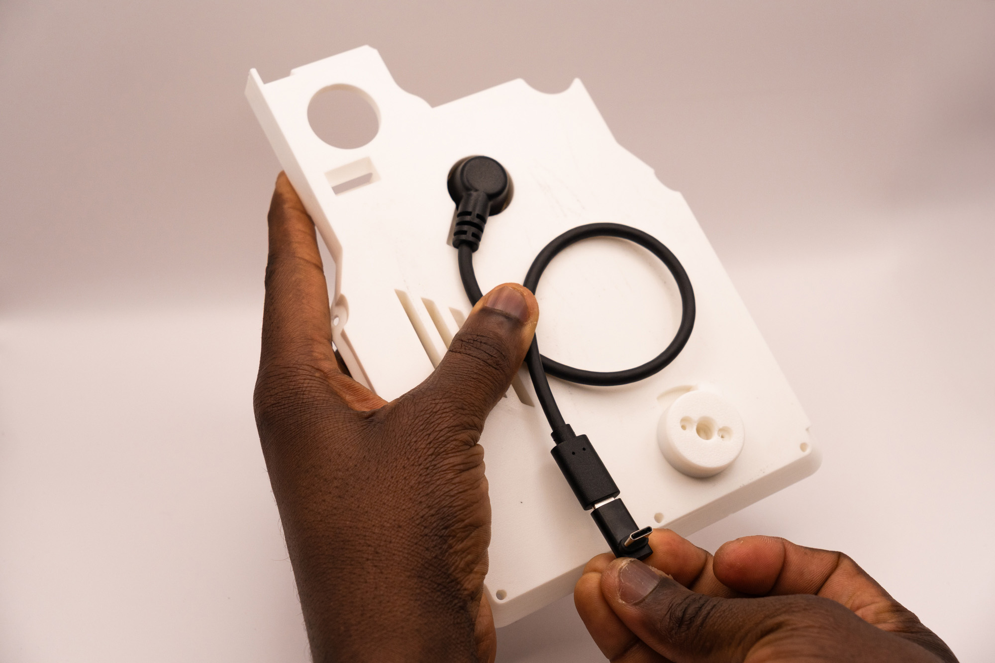
Connect the 90º USB-C adapter to the Waterproof USB-C cable and twist the cable as indicated to help avoiding collision with other parts when finishing the assembly:

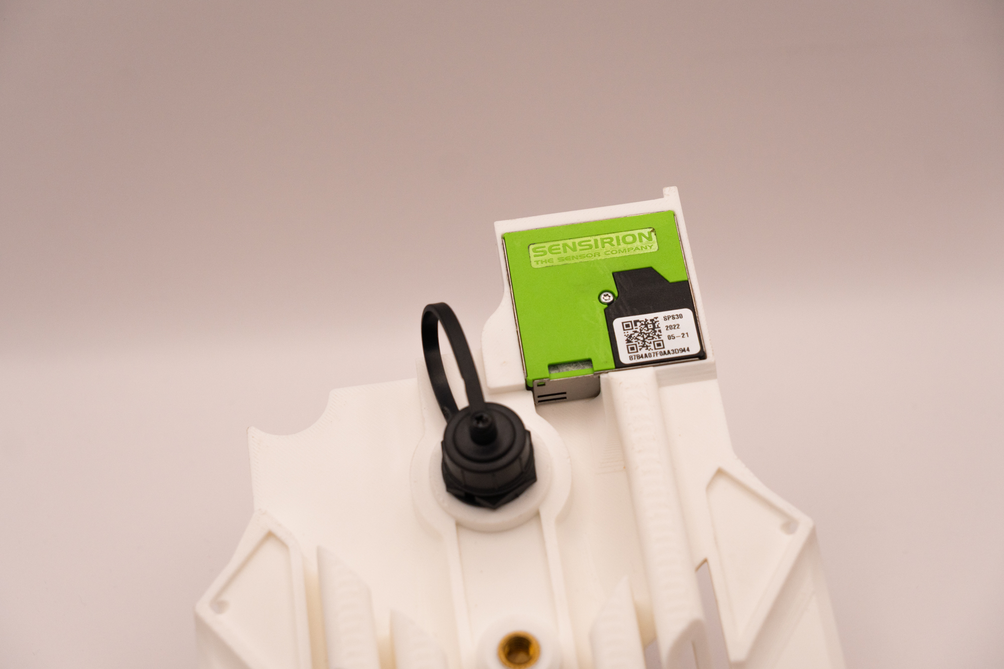
Step 11 – Particulate Sensor
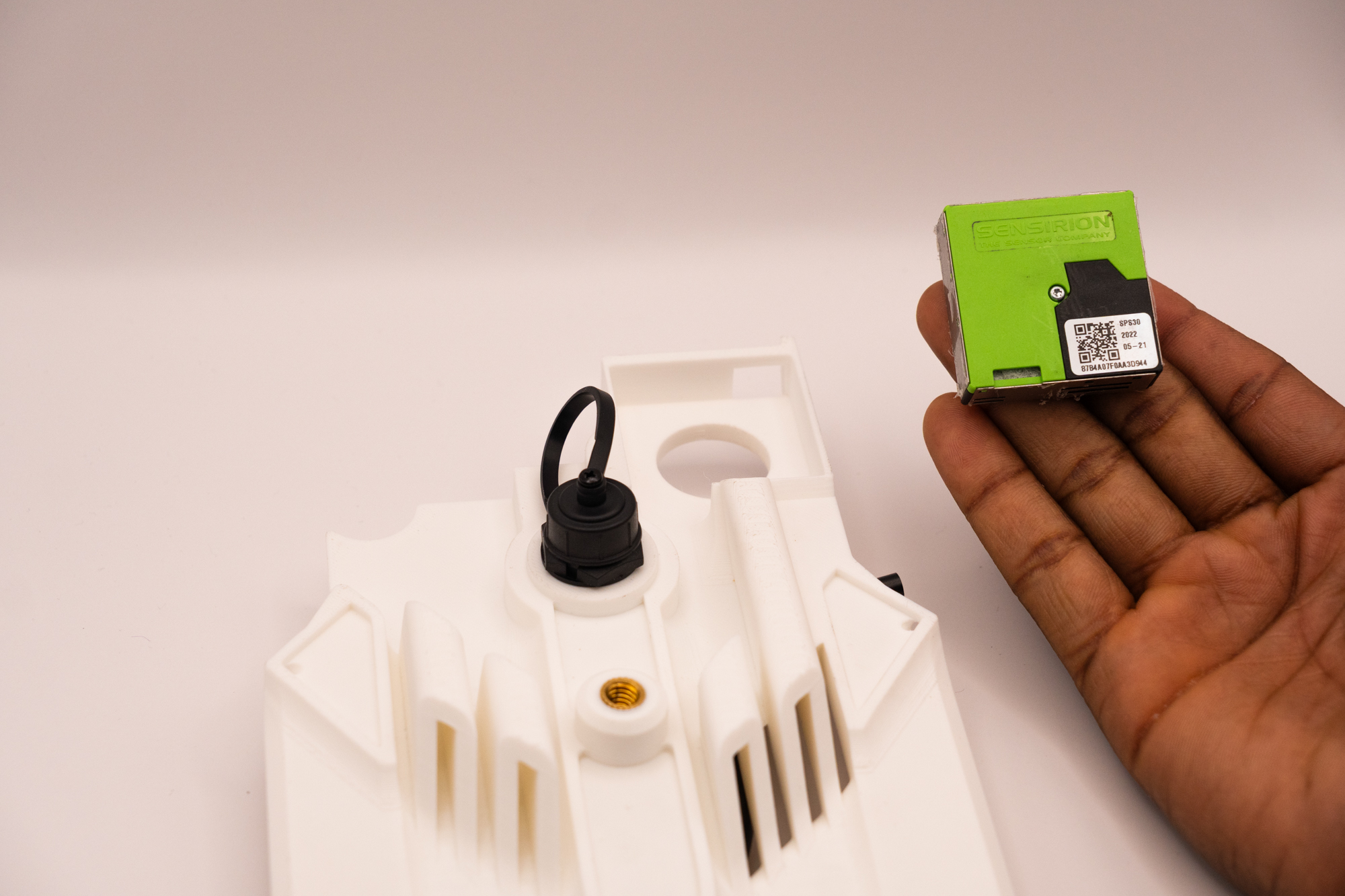
Pay attention to the correct orientation, since there are several ways for assembling it wrong.
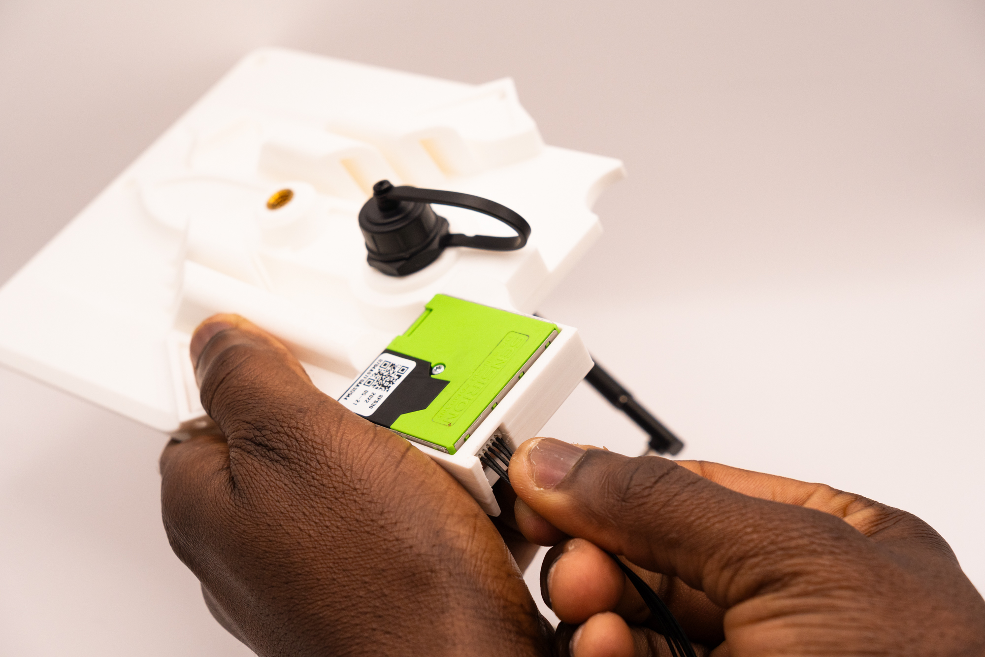
Place the Sensirion sensor into its craddle on the middle piece:
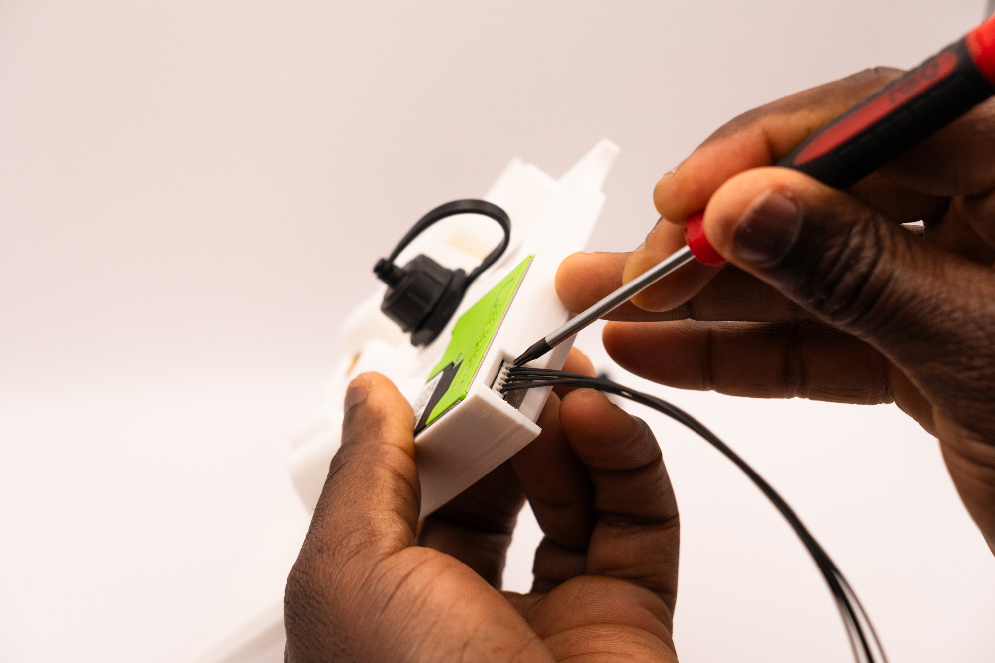
Attach the cable to the Sensirion sensor:
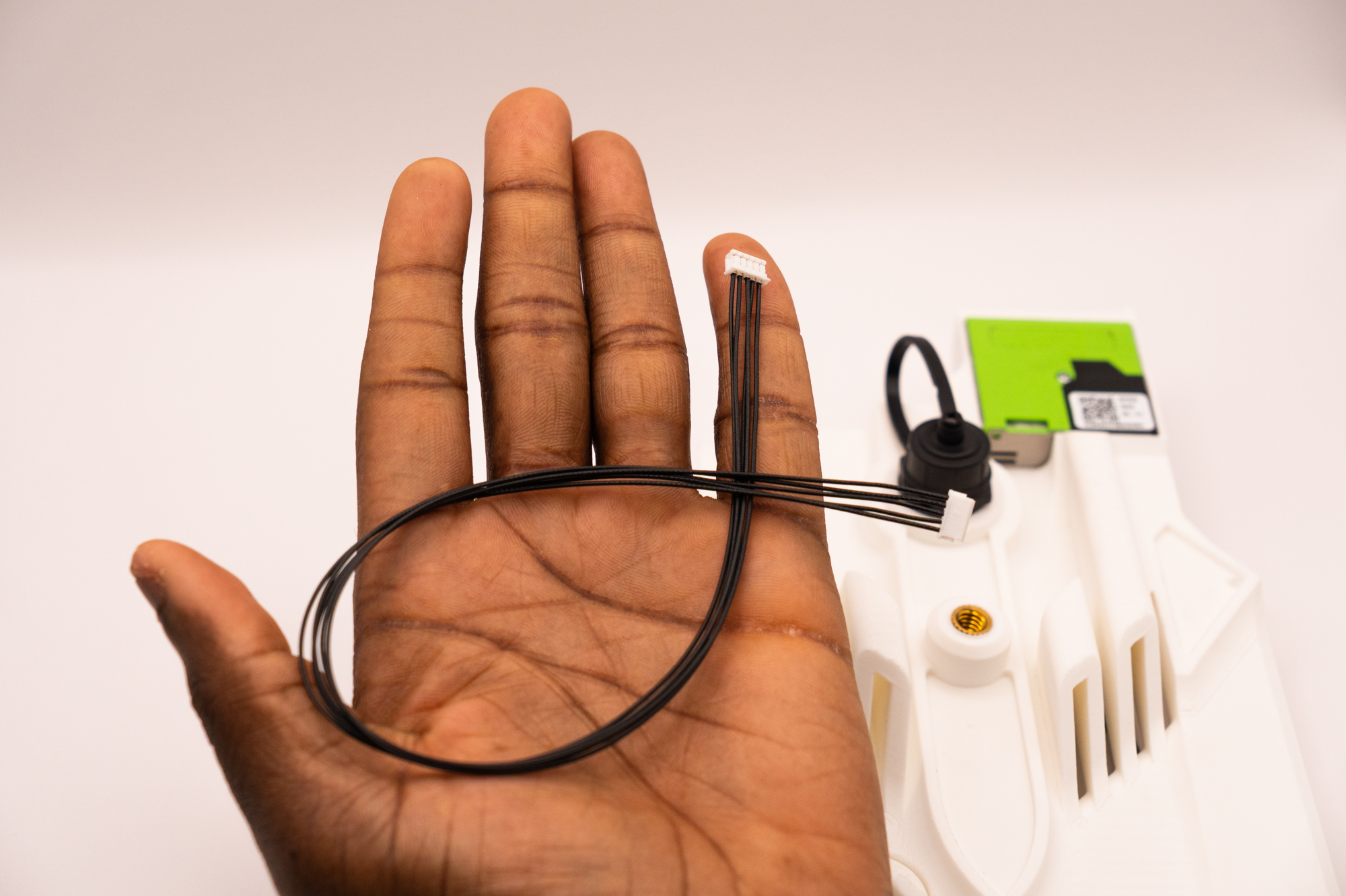
If you need, use a tweezer or screwdriver to help attaching the sensor properly to the end.
And turn the Main Board switch twice until the green light turns on ("on" position):
Roll the Sensirion cable to remove the excess and connect it to the indicate spot:
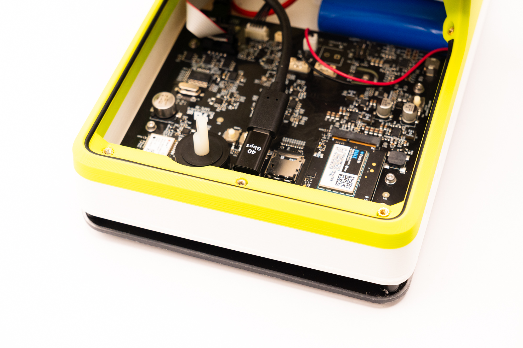
Step 12 – Switch & Closing
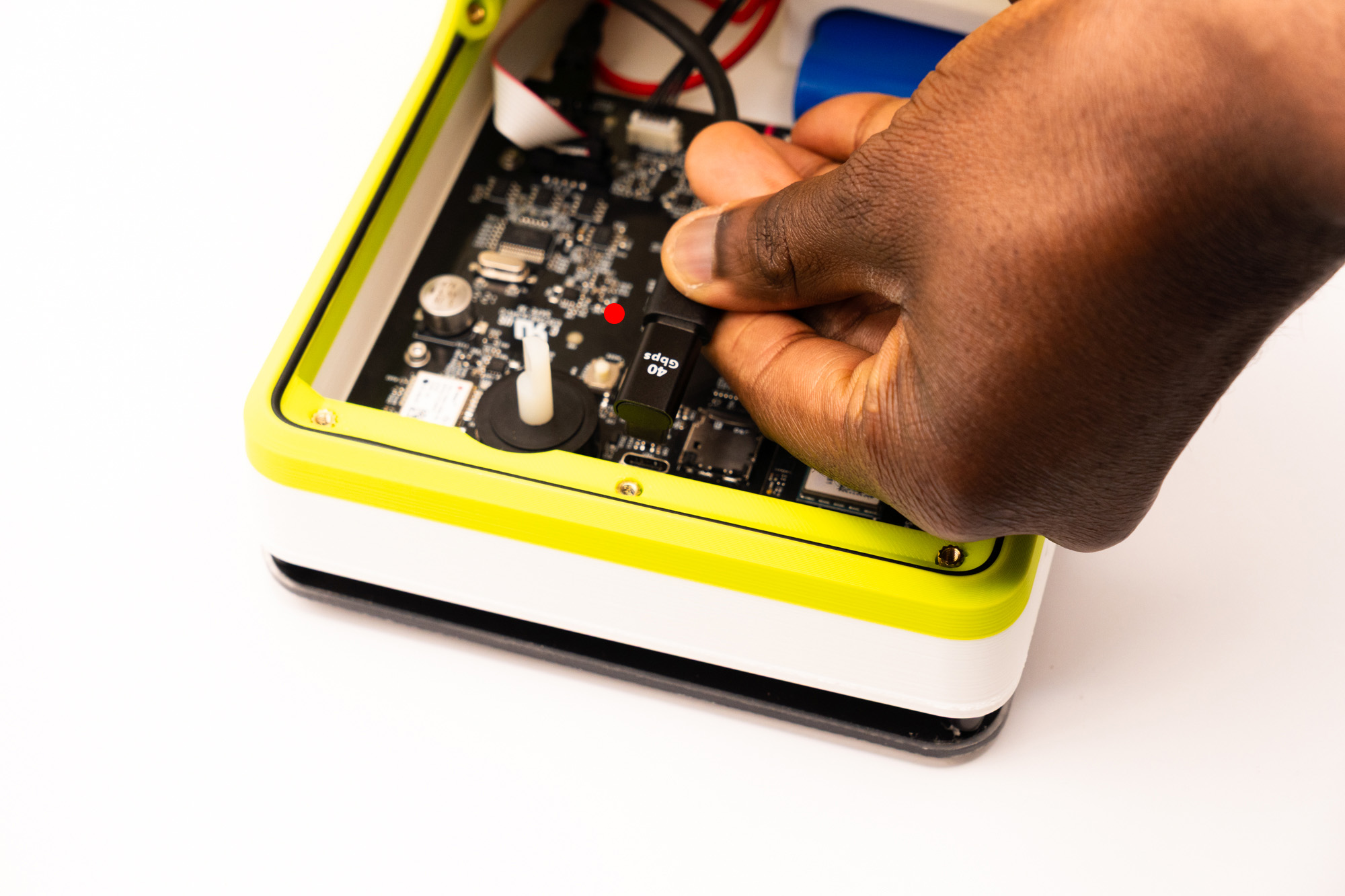
Plug in the 90º USB-C Adapter to the Main Board:
With care, align the middle and top pieces together while respecting the switch position:
Now you must move back the switch counter-clockwise to turn the device off.
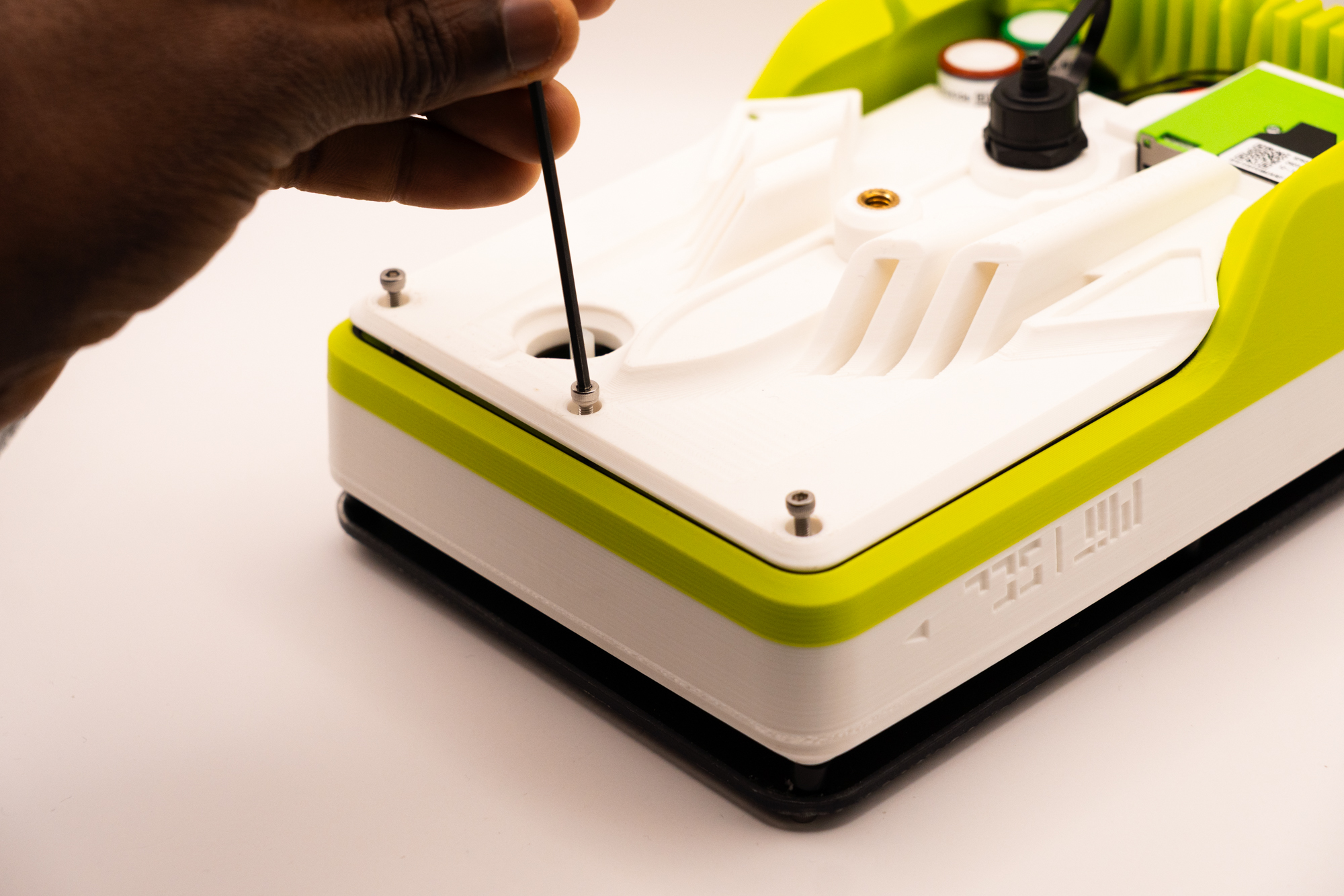
Fasten 3x M3x16 screws, joining the middle and top pieces together:
Align the switch_top with the top piece while respecting the switch position:
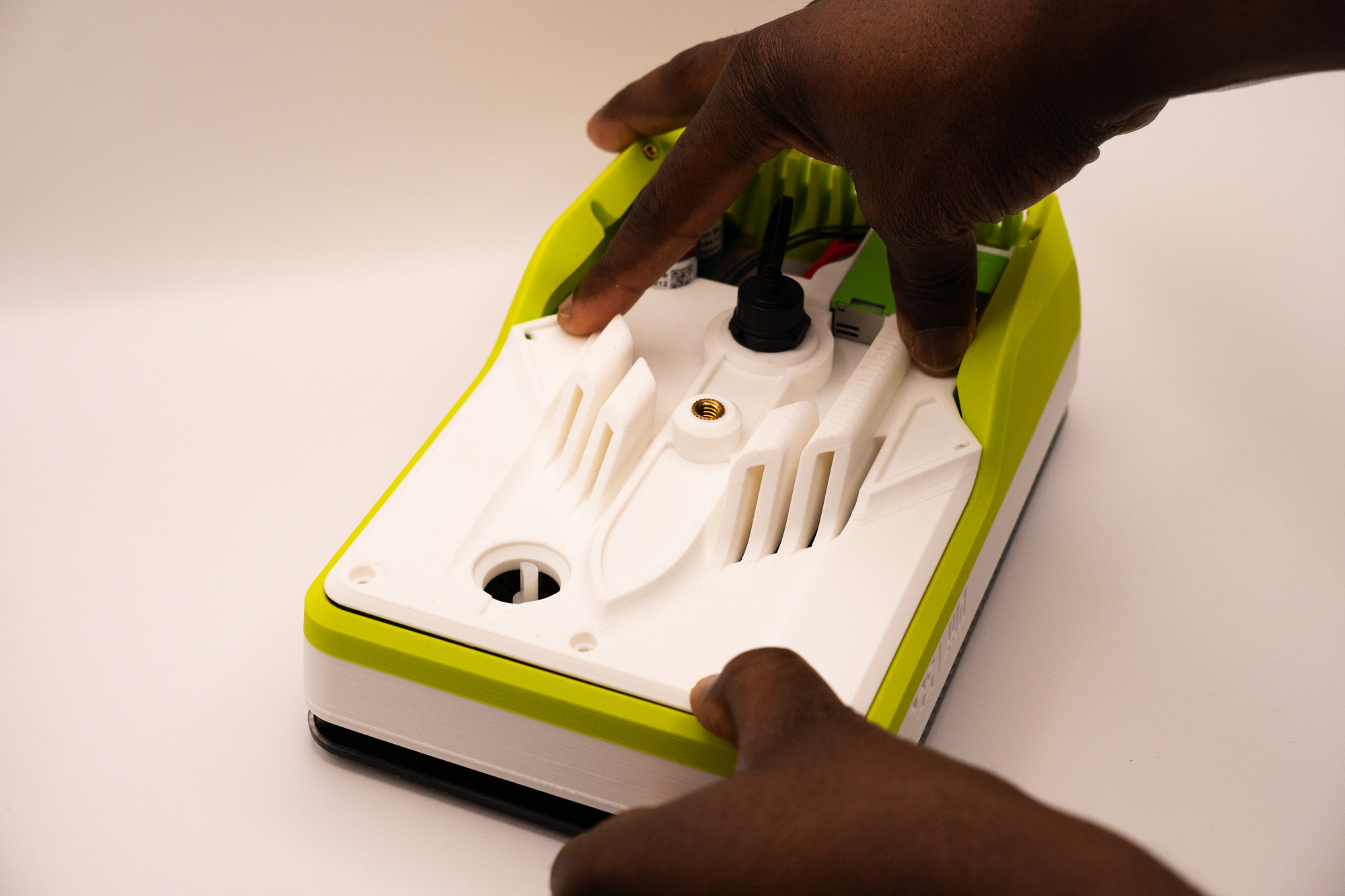
Position the bottom piece over the top and middle pieces:
Keep the cap strip out of the way:
Then insert it into the appropriate entrance on the right:
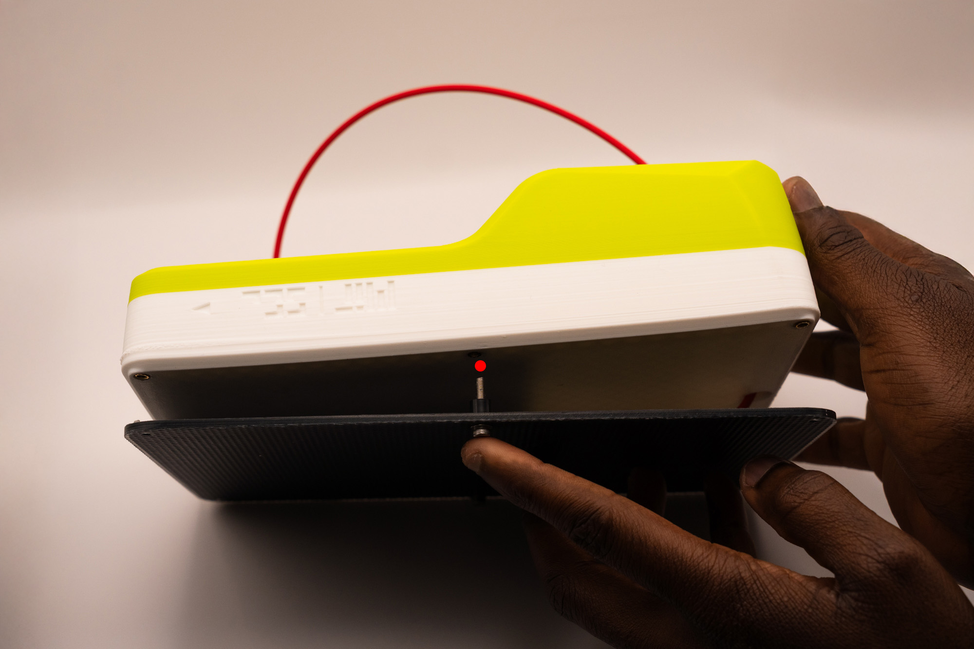
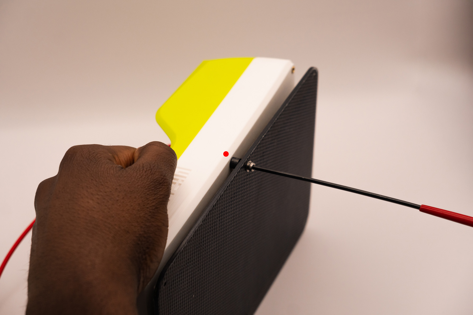
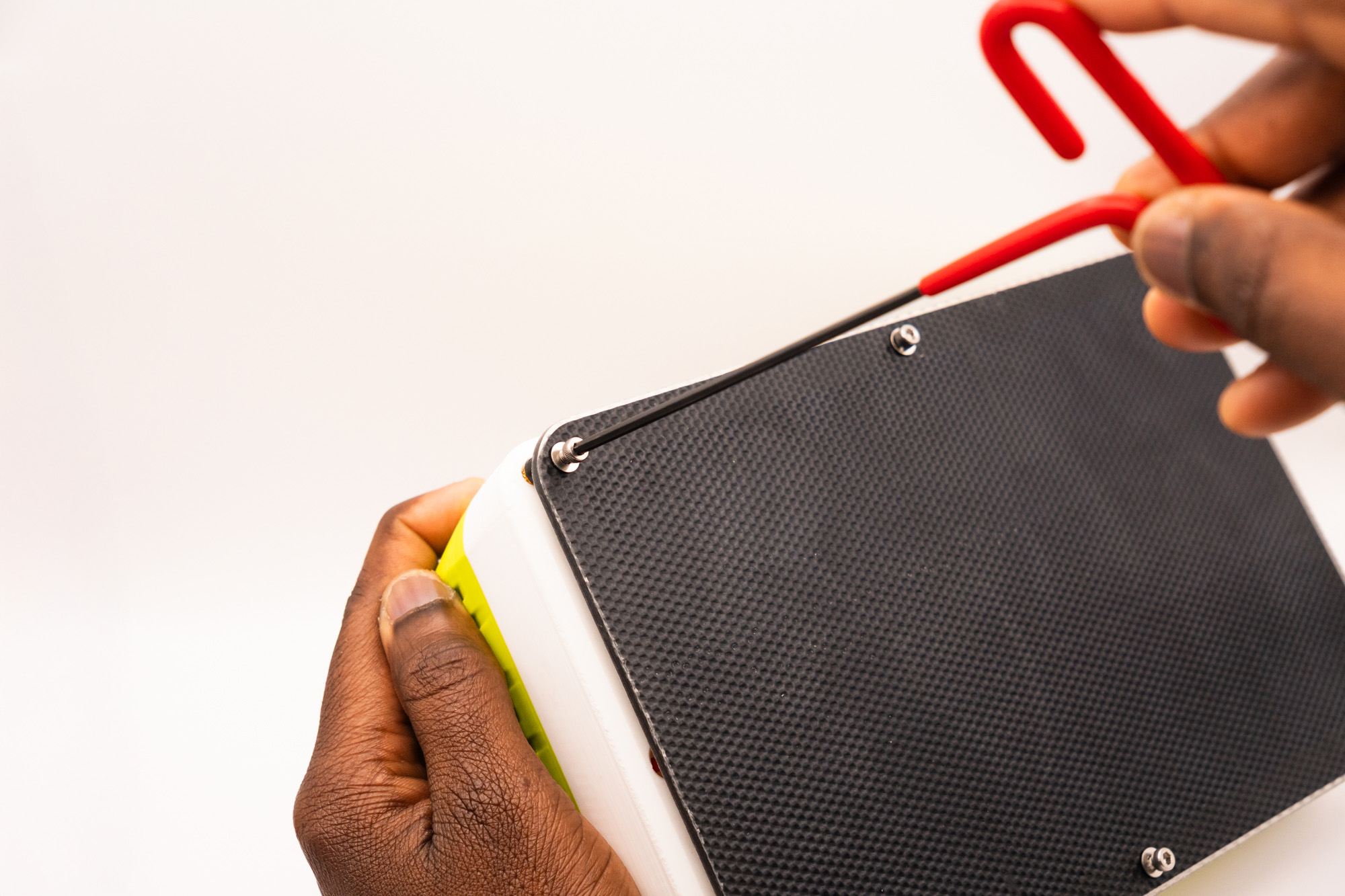
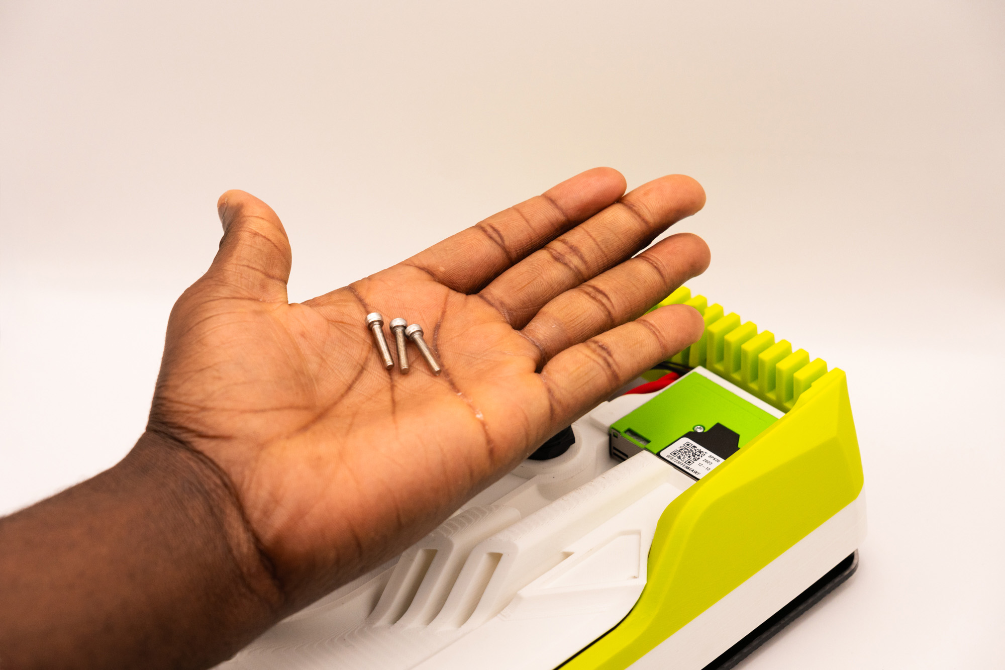
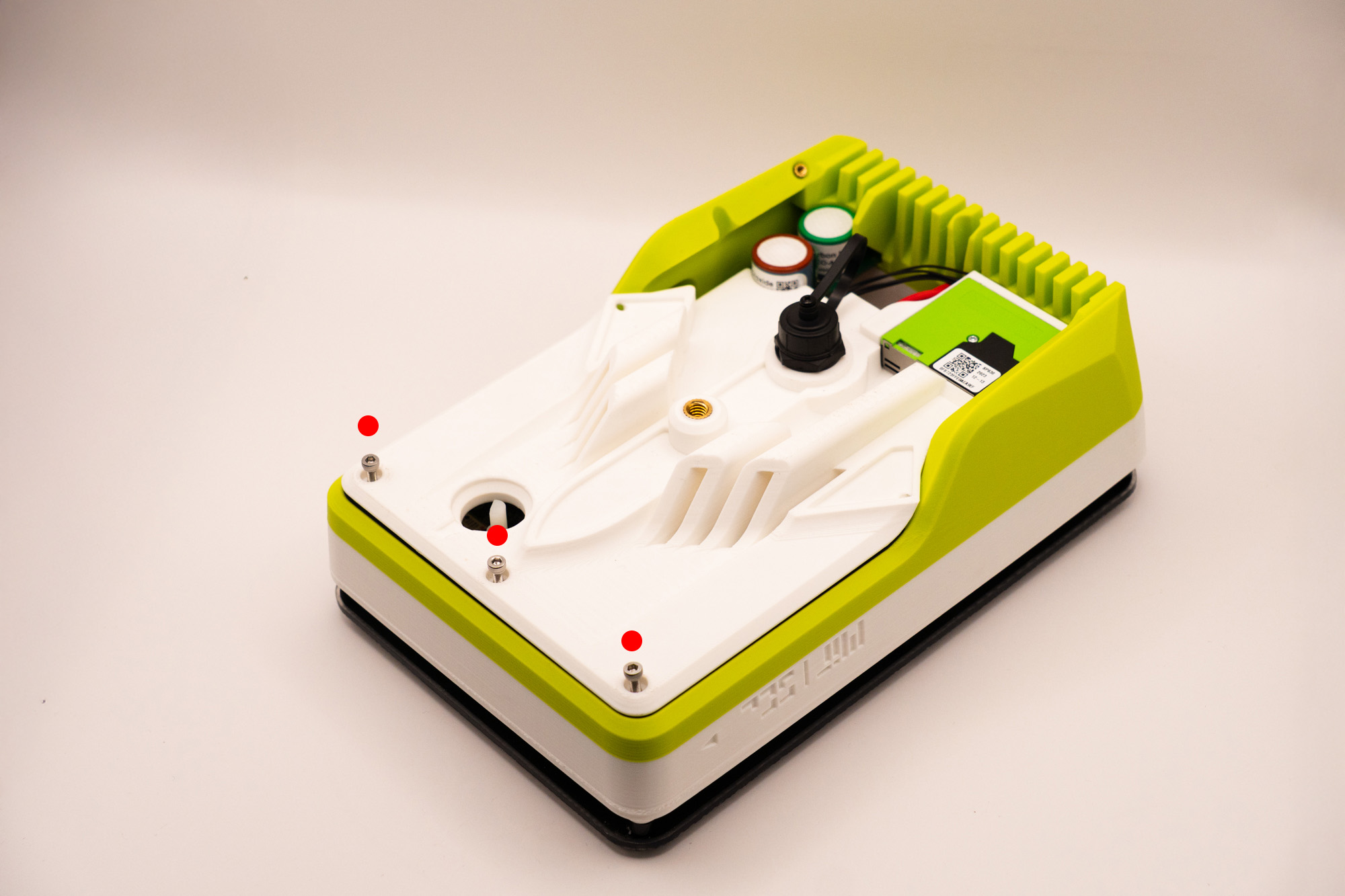
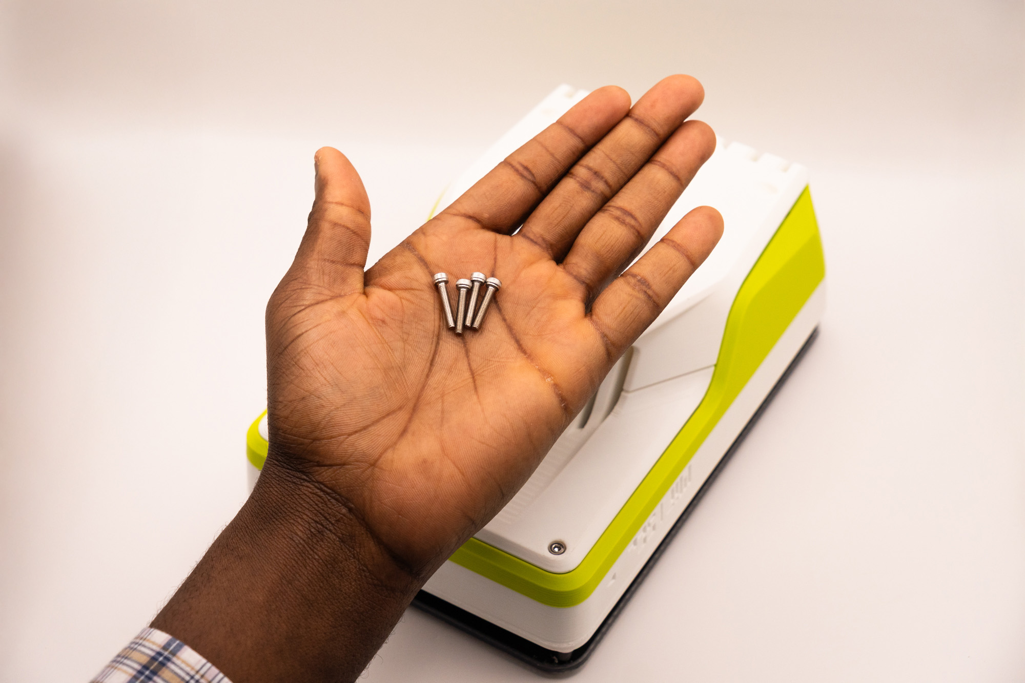
Place the last 4x M3x16 screws into the four bottom openings:
Fasten to hold it together with middle and top pieces:
Due to the angles it might be more dificult to fasten the screws than usual.
Instead of fixing one at once then proceding to the next, it is easier if each one is tightened a bit at a time.

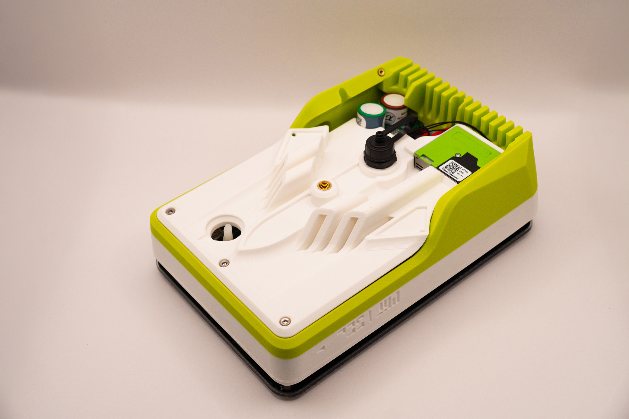
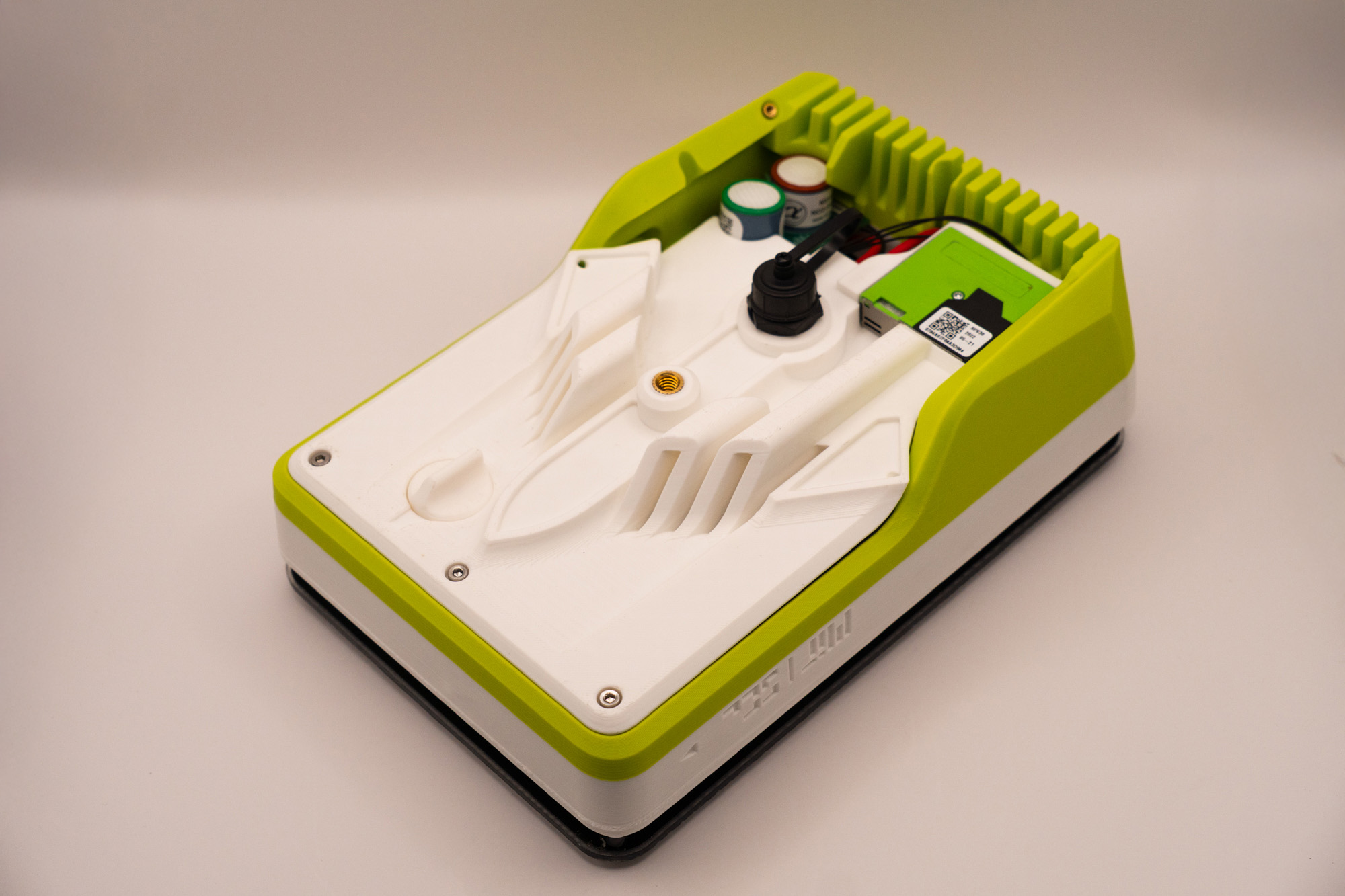
✅ Result
Make sure all seams are neatly aligned to avoid sealing issues.
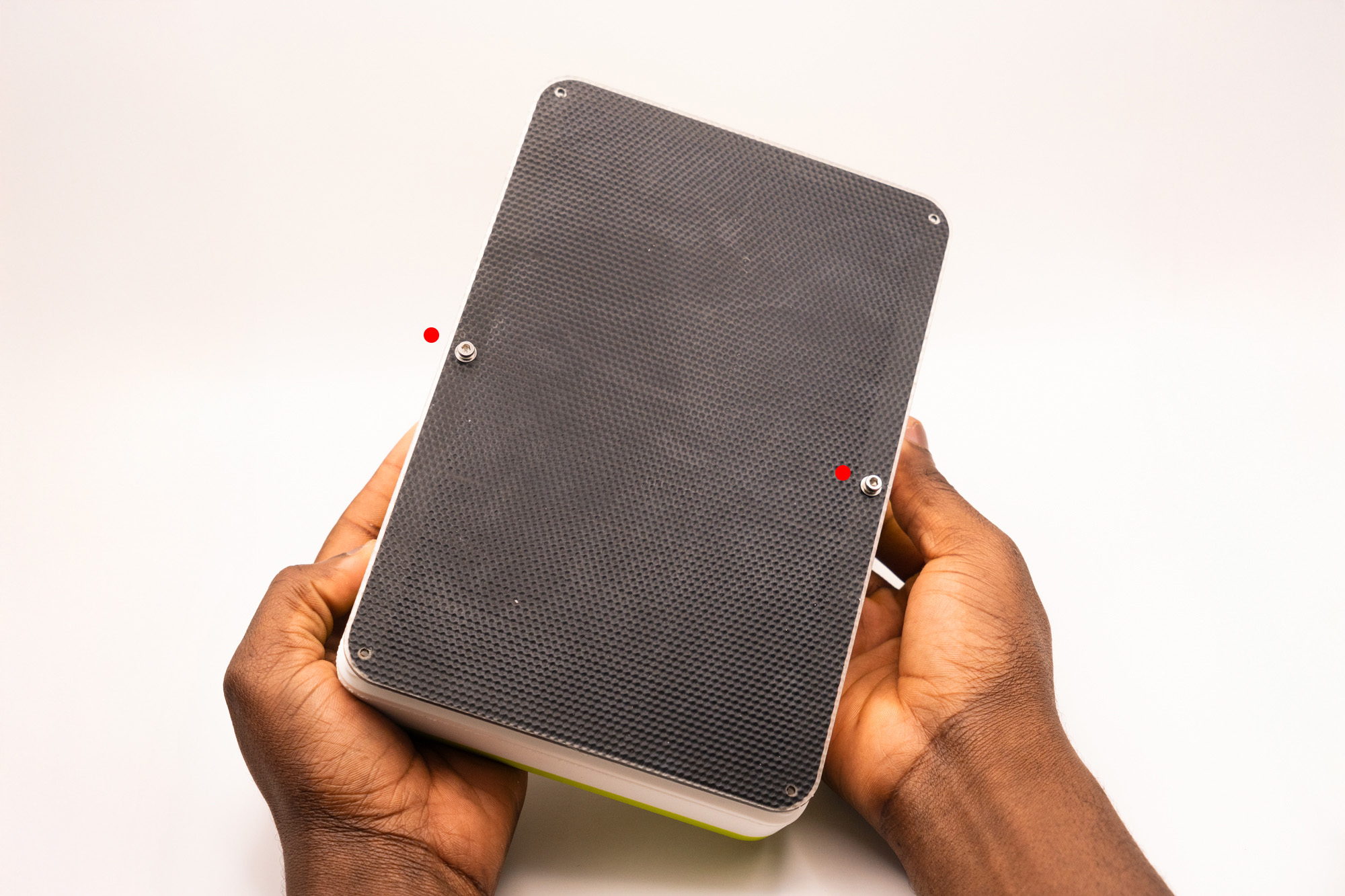
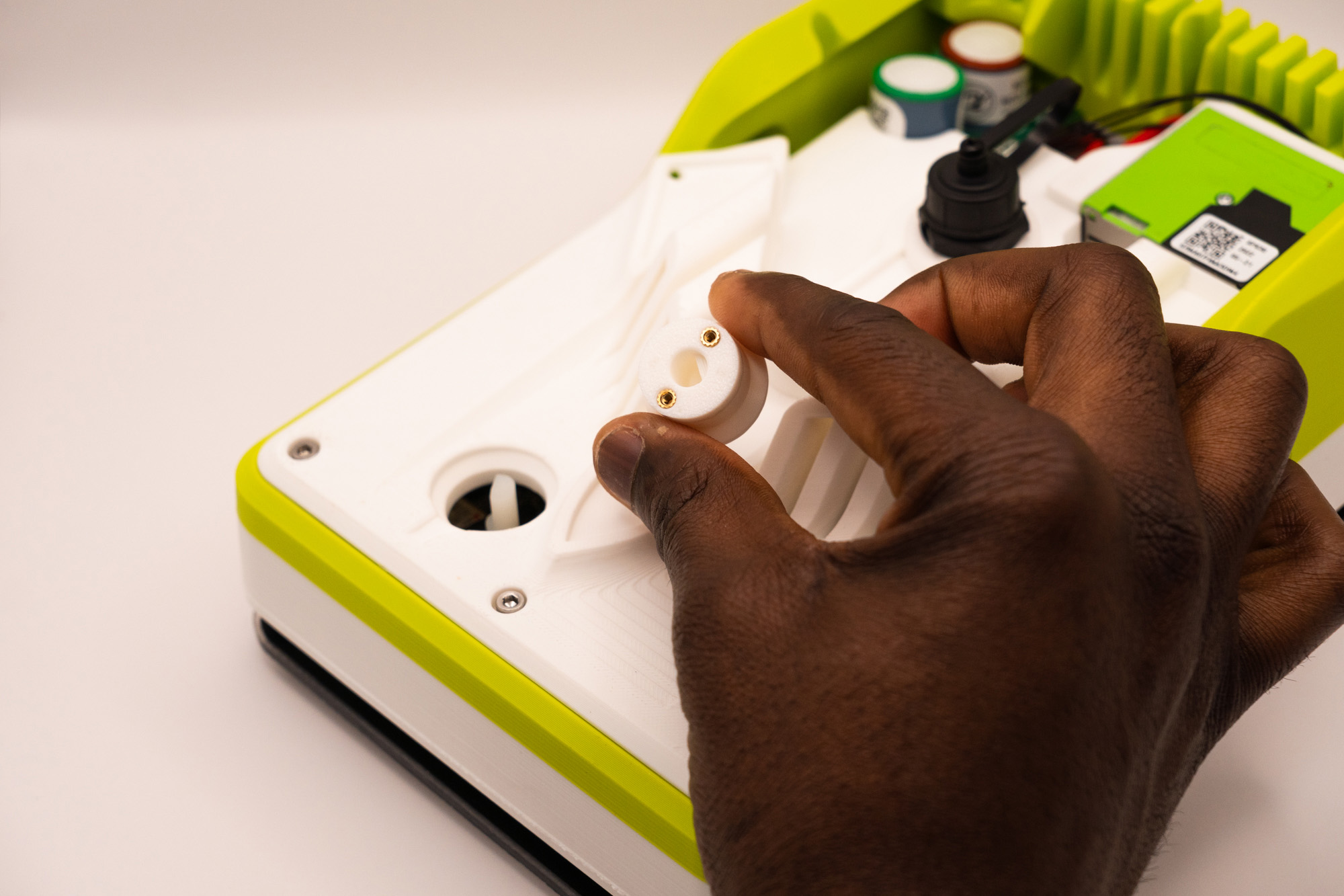
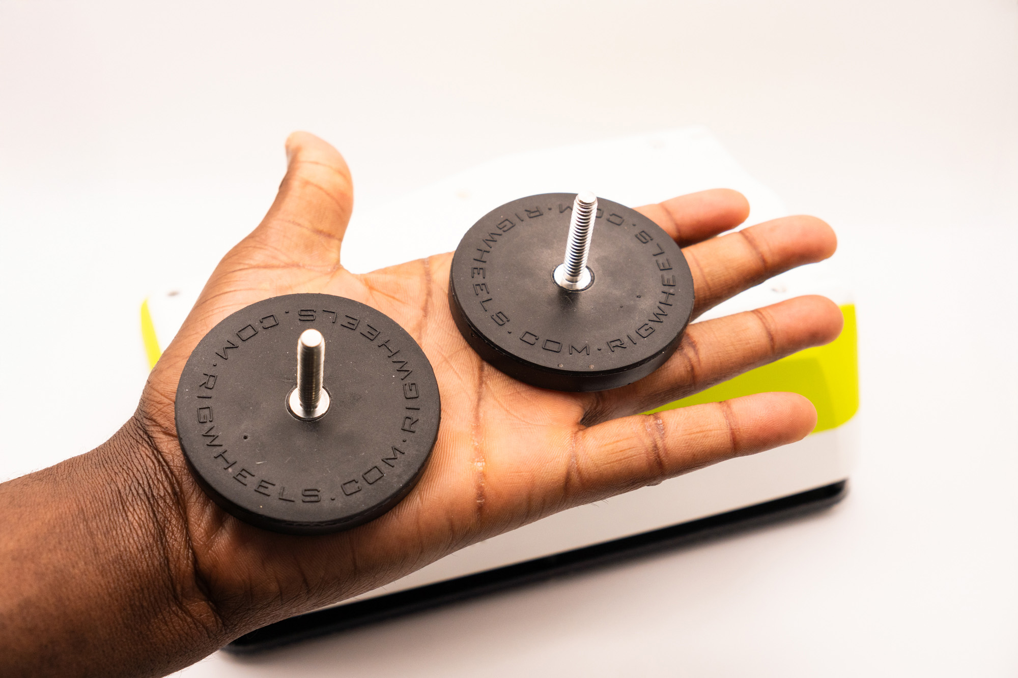
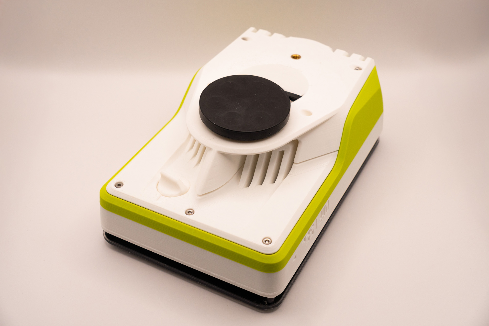
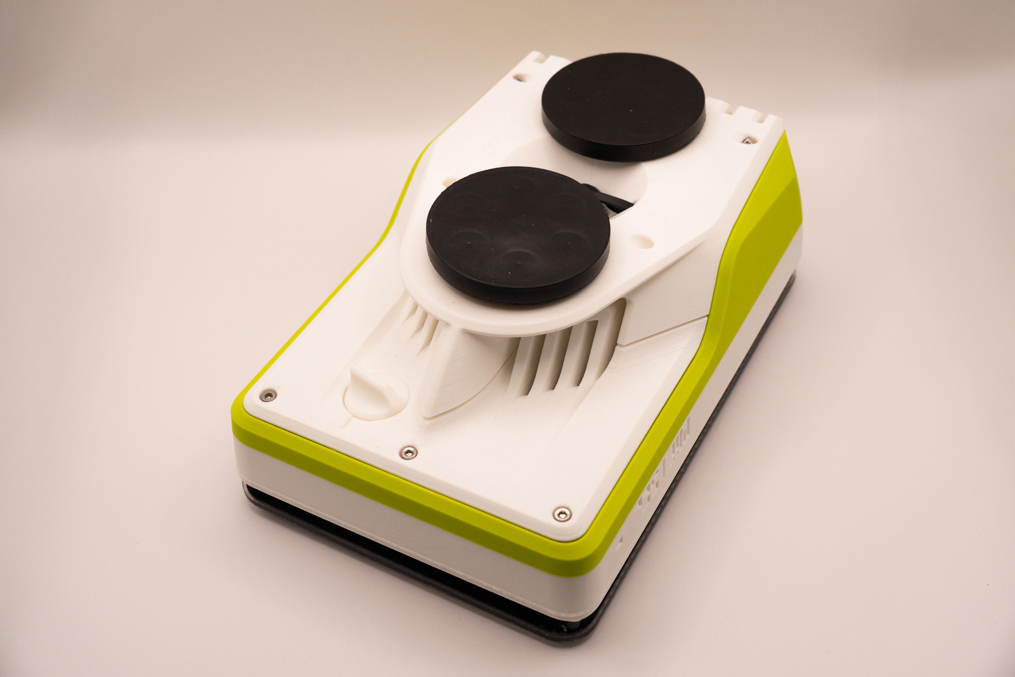
Step 13 – Magnets
Fasten both magnets into the botton piece, making sure it is well tightened:
Step 14 – Identification
It is recommended to label each unit with a unique ID to avoid data identification issues:
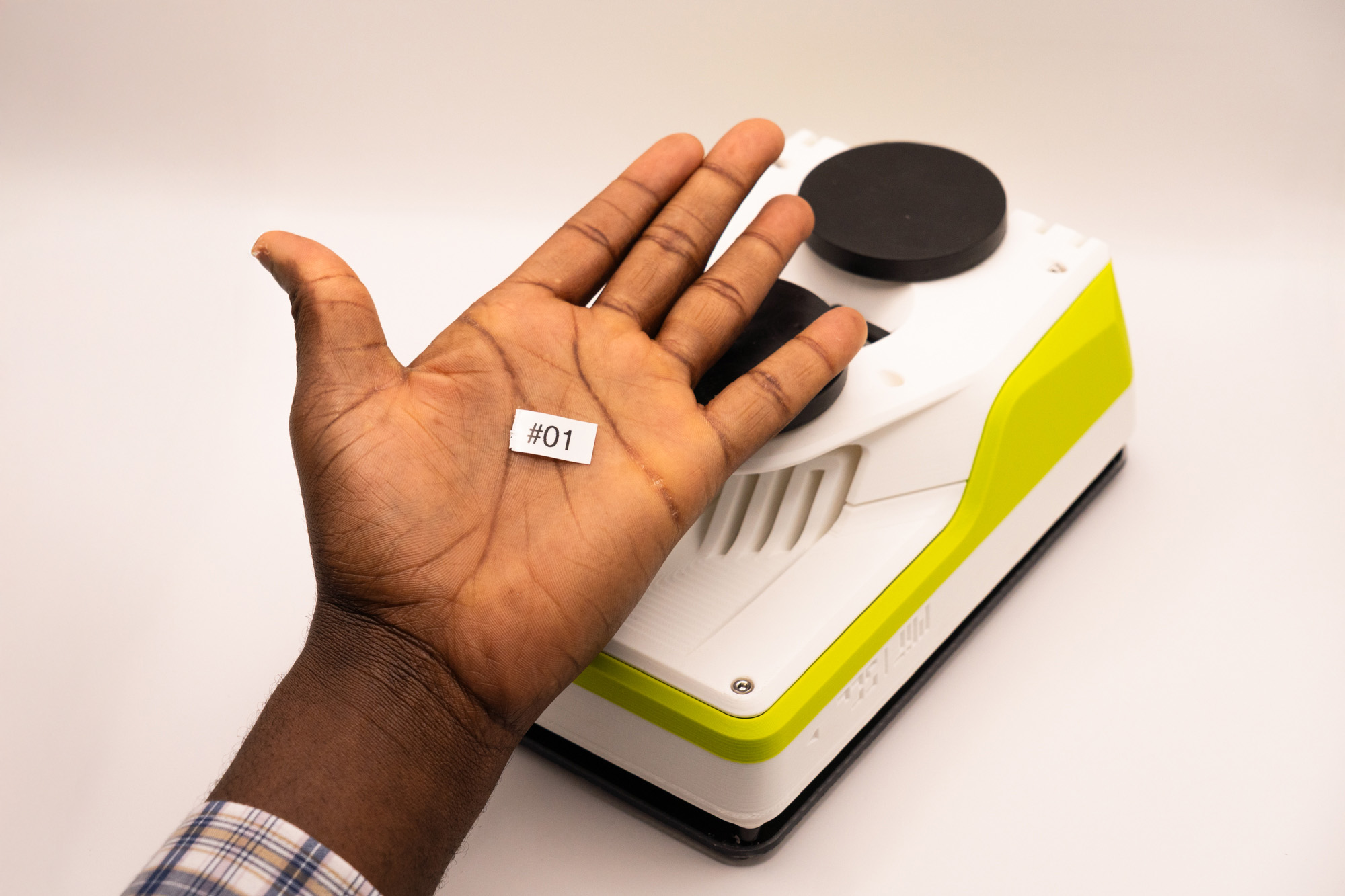
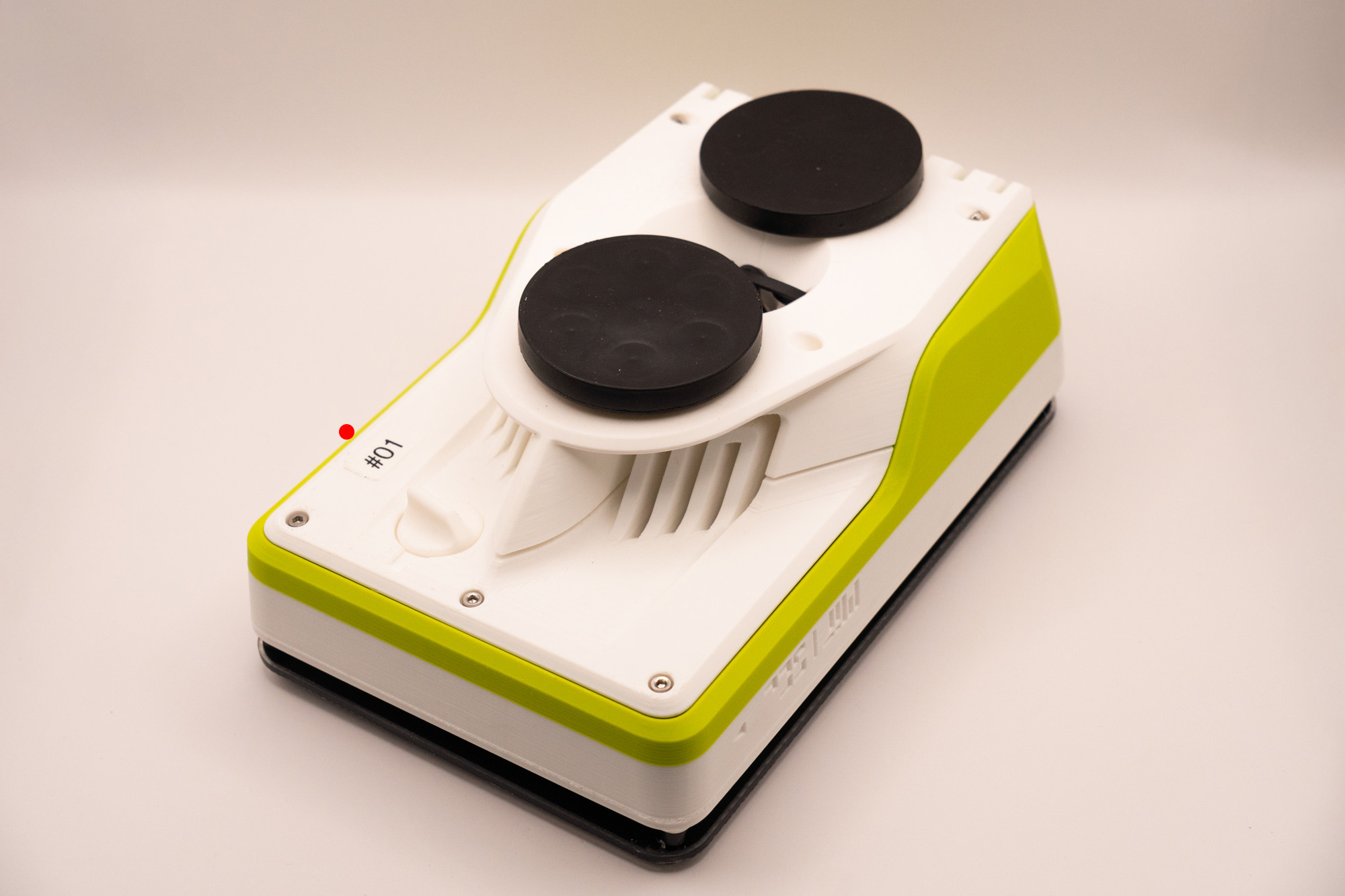
You made it!